
Audi A6 C7 (Type 4G, 2011-2018) has fuse panels at both ends of the dashboard and behind the right-hand luggage compartment trim. Depending on the engine and market, additional power distribution and engine-electronics protection may be fitted in the plenum chamber below the windscreen. The circuits can differ by model year, engine, equipment and body style.
This guide keeps the 2015 model-year layout separate from the later arrangement documented for 2016. That distinction is important for the blower, MMI, 12 V outlets and numerous control modules. Do not rely on the physical appearance of a fuse carrier alone: check the production date, equipment and actual fuse cover legend.
Where are the Audi A6 C7 fuse boxes?
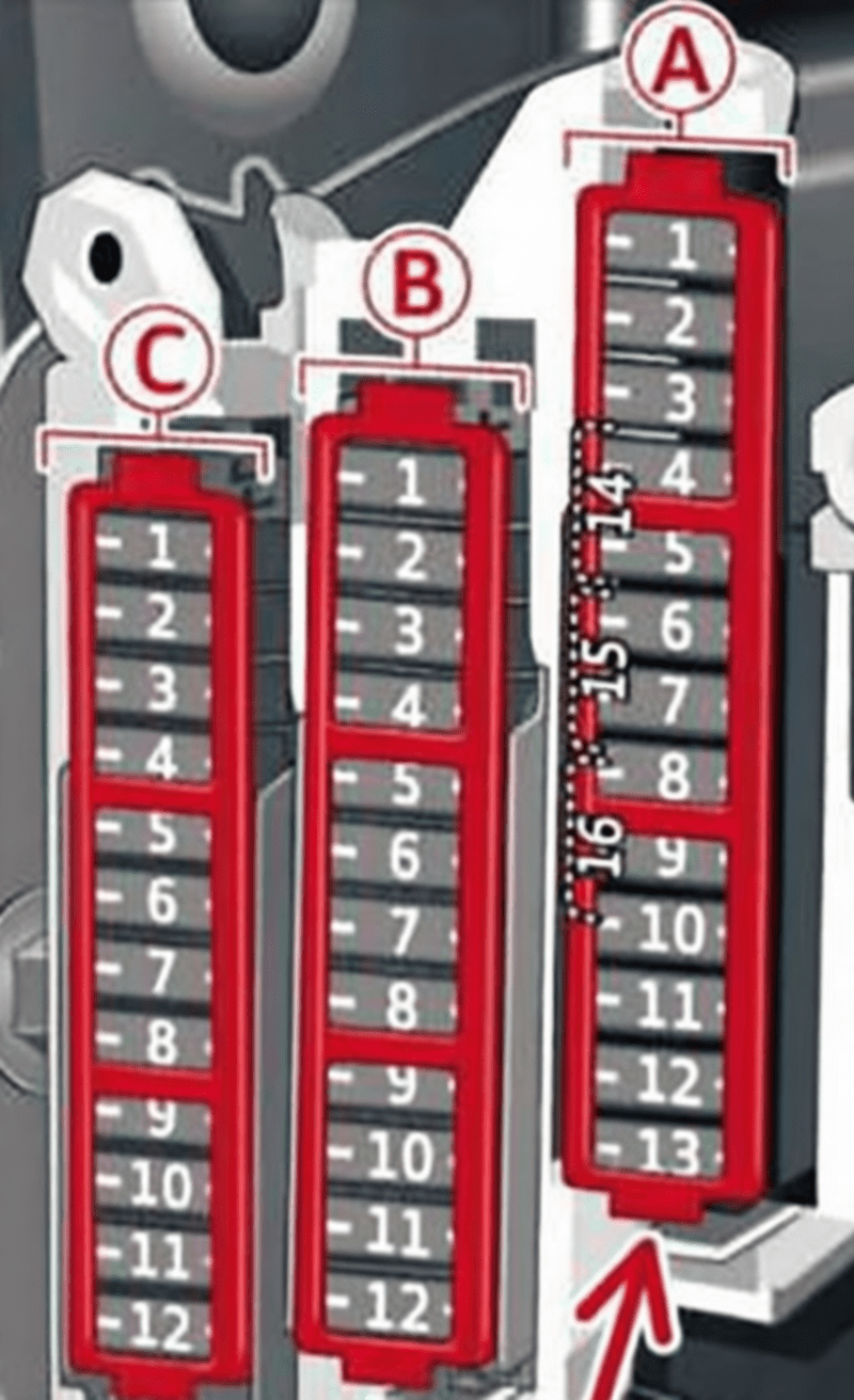
Left dashboard: with the ignition off, open the left front door, then carefully unclip the side cover of the dashboard. The three fuse strips A, B and C are behind this access panel. In left-hand-drive cars, this is the driver’s side.
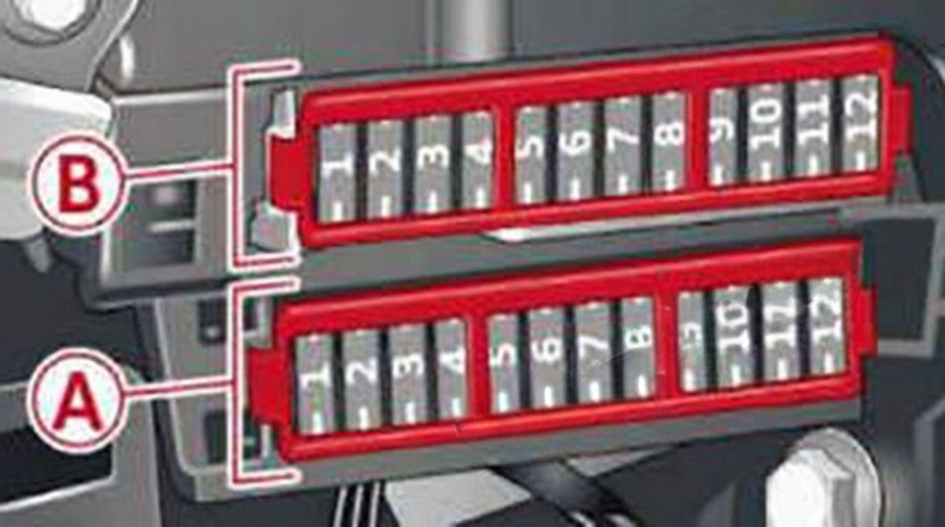
Right dashboard: open the right front door and remove the plastic cover at the far end of the dashboard. The two fuse carriers A and B are accessible without removing the glovebox.
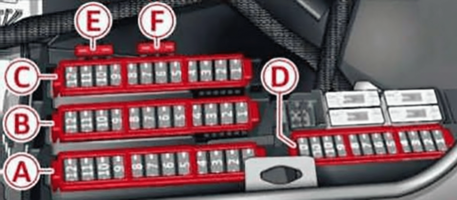
Luggage compartment: open the boot or tailgate and lift or fold back the right-side trim panel. Certain vehicles require the lower fixings to be released. The fuse sections are labelled A through F, and some configurations have additional relays.

Always switch off the ignition before replacing a fuse. Ratings separated by a slash are alternatives for specific installations, not a range from which to choose. A dash can mean an empty position or an unverified universal rating; use the fitted vehicle’s markings to decide which applies.
Fuse box diagrams and tables – Audi A6 C7 2016 configuration
Left dashboard – fuse carriers A, B and C (2016)
Carrier A includes steering, starter and driver-assistance circuits; B covers passenger-compartment and comfort electronics; C includes powertrain, door, wiper and lighting functions. Lettered carrier designations and position numbers must be read together.
| Pozycja | Amperaż [A] | Chroniony obwód / funkcja |
|---|---|---|
| Panel A | ||
| A1 | 5 | Electromechanical steering, trailer hitch, ionizer, switch panel, rear-seat heating and electronic parking brake |
| A2 | 5 | Horn, climate control, gateway and automatic dimming interior mirror |
| A3 | – | Unused / unassigned position |
| A4 | 5 | Parking assistance and headlamp levelling |
| A5 | 5 | Dynamic steering and electronic stability control (ESC) |
| A6 | 10 | Headlamps |
| A7 | 10 | Adaptive cruise control |
| A8 | 5 | Front passenger seat sensors and airbag |
| A9 | 5 | Gateway |
| A10 | 7,5 | Engine sound system, night vision, HomeLink garage opener and parking assistance |
| A11 | 10 | Video camera image processing |
| A12 | 10 | Headlamps |
| A13 | 5 | Steering column switches |
| A14 | 30 | Terminal 15 power supply – luggage compartment |
| A15 | 15 | Terminal 15 power supply – engine compartment |
| A16 | 40 | Starter motor |
| Panel B | ||
| B1 | 5 | Audio device interface and infotainment system |
| B2 | 5 | Phone amplifier / infotainment |
| B3 | 7,5 | Front passenger seat control |
| B4 | – | Unused / unassigned position |
| B5 | 5 | Airbag and electronic stability control (ESC) |
| B6 | 5 | Anti-theft alarm system |
| B7 | 5 | Electronic parking brake |
| B8 | 5 | Interior lighting |
| B9 | 5 | Windscreen camera heater and light / rain sensor |
| B10 | 5 | Driver seat lumbar support |
| B11 | 7,5 | Driver seat |
| B12 | 10 | Electronic stability control |
| B13 | 15 | Horn |
| B14 | 30 | Headlamps |
| B15 | 30 | Heated front seats |
| B16 | 35 | Dynamic steering |
| Panel C | ||
| C1 | 5 | Clutch |
| C2 | 25 / 5 | Fuel pump |
| C3 | 5 | Brake light sensor |
| C4 | 7,5 / 5 | AdBlue diesel system / engine sound module |
| C5 | 30 | Rear doors |
| C6 | 30 | Front doors |
| C7 | – | Electronic stability control (ESC); rating depends on version |
| C8 | 30 | Windscreen wiper motor |
| C9 | 35 | Lighting and washer systems, depending on equipment |
| C10 | 20 | Interior lights and air conditioning |
| C11 | 30 | Headlamps |
| C12 | 20 | Sunroof |
Right dashboard – carriers A and B (2016)
Carrier A protects selected infotainment equipment, while carrier B covers climate control, diagnostics and steering column electronics. Several unused positions are intentionally listed.
| Pozycja | Amperaż [A] | Chroniony obwód / funkcja |
|---|---|---|
| Panel A | ||
| A1 | 5 | Infotainment and CD changer |
| A2 | 5 | Infotainment display |
| A3 | – | Unused / unassigned in this configuration |
| A4 | – | Unused / unassigned in this configuration |
| A5 | – | Unused / unassigned in this configuration |
| A6 | – | Unused / unassigned in this configuration |
| A7 | – | Unused / unassigned in this configuration |
| A8 | – | Unused / unassigned in this configuration |
| A9 | – | Unused / unassigned in this configuration |
| A10 | – | Unused / unassigned in this configuration |
| A11 | 5 | Auxiliary heating on certain later electrical versions |
| A12 | – | Unused / unassigned in this configuration |
| Panel B | ||
| B1 | 10 | Climate control |
| B2 | 40 | Air-conditioning blower |
| B3 | 10 | Diagnostic interface |
| B4 | 5 | Electronic ignition lock |
| B5 | 5 | Electronic steering column lock |
| B6 | 10 | Steering column switch module |
| B7 | 25 | Electric steering column adjustment |
| B8 | 5 | Light switch |
| B9 | 5 | Head-up display |
| B10 | 5 | Instrument cluster |
| B11 | 5 | Infotainment and DVD changer |
| B12 | – | Unused / unassigned in this configuration |
Right luggage compartment – carriers A-F (2016)
These carriers include parking-brake circuits, rear and front door equipment, seat heating, sound and telematics modules, tailgate electronics and equipment-specific slots. The exact fitted fuses vary with engine, specification and body style.
| Pozycja | Amperaż [A] | Chroniony obwód / funkcja |
|---|---|---|
| Panel A | ||
| A1 | 15 / 25 | Trailer hitch / 220 V socket |
| A2 | 10 / 25 | Trailer hitch / cooled cup holder |
| A3 | 5 / 25 | Trailer hitch / front passenger seat adjustment |
| A4 | 30 | Electromechanical parking brake |
| A5 | 30 | Electromechanical parking brake |
| A6 | 30 | Front passenger door |
| A7 | 30 | Rear exterior lighting |
| A8 | 20 | Central locking and soft-close assist |
| A9 | 15 | Heated front seats |
| A10 | 5 | Unused / unassigned position |
| A11 | 30 | Rear seat heating and climate control |
| A12 | 15 | Towbar |
| Panel B | ||
| B1 | 25 | Left seatbelt pretensioner |
| B2 | 25 | Right seatbelt pretensioner |
| B3 | 30 | AdBlue tank (diesel) / fuel pump |
| B4 | 10 | AdBlue tank (diesel) / engine mounting (petrol) |
| B5 | 1 | Tailgate opening control module |
| B6 | 15 | Air suspension and adaptive dampers |
| B7 | 30 | Rear passenger door |
| B8 | 30 | Rear lights |
| B9 | 30 | Luggage compartment lid |
| B10 | 15 | Rear-seat multimedia system |
| B11 | – | Unused / unassigned position |
| B12 | 20 | Rear spoiler (Sportback where fitted), opening roof or panoramic glass roof – equipment dependent |
| Panel C | ||
| C1 | 5 | Infotainment |
| C2 | 5 | Infotainment |
| C3 | 7,5 | Infotainment and auto-dimming interior rear-view mirror |
| C4 | 5 | Surround-view camera controller, where fitted |
| C5 | 5 | TV tuner |
| C6 | 5 | Fuel-tank leak detection system |
| C7 | 20 | Power outlets |
| C8 | 5 | Auxiliary parking heater |
| C9 | – | Unused / unassigned position |
| C10 | 5 | Front passenger seat lumbar support |
| C11 | 5 | Unused / unassigned position |
| C12 | 5 | Infotainment |
| Panel D | ||
| D1 | 5 | Air suspension, adaptive dampers, sport differential and electronic parking brake |
| D2 | 5 | Clutch pedal position sensor / automatic transmission |
| D3 | 5 | Seats |
| D4 | 15 | Rear wiper (Avant) |
| D5 | 5 | Side assist / blind-spot monitoring |
| D6 | 10 | Engine sound system |
| D7 | 30 | Infotainment / sound amplifier |
| D8 | 5 | Gateway |
| D9 | 35 | All-wheel-drive control module / sport differential |
| D10 | 10 | Climate control |
| D11 | 15 / 30 | Tyre pressure monitoring / auxiliary parking heater |
| D12 | 10 | Start-stop system |
| Panel E | ||
| E1 | – | Special equipment / rear seats |
| Panel F | ||
| F1 | 40 | Heated rear window |
Relays and high-current protection – selected 2016 variants
Relay sockets are shown with a dash for amperage; the CAN disconnect connector U1 is a wiring component rather than a blade fuse.
| Pozycja | Amperaż [A] | Chroniony obwód / funkcja |
|---|---|---|
| 1a | 40 | Main protection for suspension level-control system |
| 1b | 50 | Main terminal 30 supply |
| R2 | – | Rear-window heater relay |
| R3 | – | Power outlet relay |
| R4 | – | Terminal 15 supply relay |
| R5 | – | Air suspension compressor relay |
| R6 | – | AdBlue or fuel-pump relay, depending on engine |
| U1 | – | CAN disconnect connector – wiring component, not a fuse |
2015 model-year fuse assignment – separate configuration
The earlier 2015 arrangement can use different functions at corresponding fuse numbers. The next three complete charts retain all spare sockets and alternative equipment-dependent ratings. The 2016 illustrations above show similar physical carriers, but do not prove identical electrical assignments.
Left dashboard fuse box – 2015
Left-side carriers A, B and C include the starter, engine and transmission related feeds, dynamic steering, door modules, seats and the front wiper motor.
| Pozycja | Amperaż [A] | Chroniony obwód / funkcja |
|---|---|---|
| Panel A | ||
| A1 | 5 | ESP, parking brake, seats and hill-start assistance |
| A2 | 5 | Automatically dimming rear-view mirror |
| A3 | 10 | Diesel exhaust system |
| A4 | 5 | Suspension height-control sensor |
| A5 | 5 | ABS / ESC controller |
| A6 | 5 | Air conditioning and sensors |
| A7 | 10 | Adaptive cruise control |
| A8 | 5 | Airbags and passenger seat sensor |
| A9 | 5 | Gateway |
| A10 | 5 | HomeLink and night vision |
| A11 | 10 | Driver assistance camera |
| A12 | 5 | Dynamic steering |
| A13 | 15 | Ignition-switched supply |
| A14 | 30 | Ignition-switched power – luggage compartment |
| A15 | 15 | Ignition-switched power – engine bay |
| A16 | 40 | Starter motor |
| Panel B | ||
| B1 | 5 | Gateway |
| B2 | 10 | Air conditioning |
| B3 | 10 | Electronic stability control (ESC) |
| B4 | 30 | Driver door control module |
| B5 | 7,5 | Driver seat adjustment |
| B6 | 35 | Dynamic steering |
| B7 | 20 | Sunroof |
| B8 | 15 | Left rear door |
| B9 | 5 | Passenger seat lumbar support |
| B10 | 5 | Tyre pressure monitoring |
| B11 | 20 | Sunroof / active spoiler |
| B12 | 15 | Driver door module |
| Panel C | ||
| C1 | 5 | Clutch pedal sensor |
| C2 | 25 | Fuel pump |
| C3 | 5 | Brake light switch |
| C4 | 5 / 7,5 | AdBlue (diesel) or exhaust flaps |
| C5 | 30 | Left rear door |
| C6 | 7,5 | Front passenger seat adjustment |
| C7 | 15 | Horn |
| C8 | 30 | Windscreen wipers |
| C9 | 5 | Rain and light sensor |
| C10 | 5 | Driver seat lumbar support |
| C11 | 15 | Front passenger door |
| C12 | 15 | Right rear door |
Right dashboard fuse box – 2015
For 2015, the right-side A carrier includes the 40 A blower supply at A2. The B carrier includes display and MMI equipment, head-up display and selected adaptive lighting electronics.
| Pozycja | Amperaż [A] | Chroniony obwód / funkcja |
|---|---|---|
| Panel A | ||
| A1 | 10 | Air-conditioning control unit |
| A2 | 40 | Blower motor |
| A3 | 10 | OBD diagnostics |
| A4 | 5 | Electronic ignition switch |
| A5 | 5 | Steering column adjustment |
| A6 | 10 | Steering column electronics |
| A7 | 25 | Electric steering column adjustment |
| A8 | 5 | Light switch |
| A9 | – | Unused position |
| A10 | – | Unused position |
| A11 | – | Unused position |
| A12 | – | Unused position |
| Panel B | ||
| B1 | 5 | Head-up display |
| B2 | 5 | MMI display |
| B3 | 5 | CD/DVD changer |
| B4 | 7,5 | MMI control unit |
| B5 | 5 | Card reader on selected markets |
| B6 | 5 | Instrument cluster |
| B7 | 5 | Steering column electronics |
| B8 | 5 / 7,5 | Headlamp levelling / adaptive front lighting (AFS) |
| B9 | – | Unused position |
| B10 | 7,5 | Left adaptive headlamp |
| B11 | 5 | Auxiliary heating |
| B12 | – | Unused position |
Luggage compartment fuse box – 2015
This version retains a separate allocation for 12 V sockets at B3 and B4, along with the parking brake, door control systems, audio electronics, air suspension and optional rear accessories.
| Pozycja | Amperaż [A] | Chroniony obwód / funkcja |
|---|---|---|
| Panel A | ||
| A1 | – | Towbar / 220 V socket depending on equipment |
| A2 | – | Towbar / heated cup holder depending on equipment |
| A3 | – | Towbar / rear seat adjustment depending on equipment |
| A4 | 30 | Parking brake |
| A5 | 30 | Parking brake |
| A6 | 30 | Front passenger door |
| A7 | 30 | Rear lights |
| A8 | 20 | Sunshade, soft-close, tailgate and keyless entry |
| A9 | 15 | Electric seat adjustment |
| A10 | 5 | Parking sensors |
| A11 | 30 | Heated rear seats |
| A12 | – | Towbar, where equipped |
| Panel B | ||
| B1 | 25 | Left seatbelt pretensioner |
| B2 | 25 | Right seatbelt pretensioner |
| B3 | 20 | 12 V accessory socket / cigarette lighter |
| B4 | 20 | 12 V socket |
| B5 | 5 | Parking brake |
| B6 | 15 | Air suspension |
| B7 | 30 | Right rear door |
| B8 | 30 | Rear lights |
| B9 | 30 | Electric tailgate |
| B10 | 5 | Phone |
| B11 | 30 | Audio amplifier |
| B12 | 20 | Spoiler on applicable body variants |
| Panel C | ||
| C1 | 20 / 30 | Radio, amplifier and MMI |
| C2 | 5 | Fuel-tank leak detection |
| C3 | – | Unused position |
| C4 | 10 / 15 | Battery / energy management controller |
| C5 | – | Unused position |
| C6 | 35 | Battery cooling fan |
| C7 | 7,5 | Radio |
| C8 | 7,5 | Rear multimedia |
| C9 | 5 / 15 | Auto-dimming mirror / battery equipment |
| C10 | 5 | Parking assistance |
| C11 | – | TV tuner, equipment dependent |
| C12 | – | Unused position |
| Panel D | ||
| D1 | 5 | Audi pre sense |
| D2 | 5 | Parking brake |
| D3 | 5 | Air suspension |
| D4 | 7,5 | Automatic transmission |
| D5 | 5 | Parking assistance |
| D6 | 5 | Rear multimedia |
| D7 | 5 | Start-stop system |
| D8 | 5 | Lane-change assist |
| D9 | 5 | Gateway and vehicle electrical system |
| D10 | 5 | Sport differential |
| D11 | – | Rear wiper on applicable bodies |
| D12 | – | Unused position |
| Panel E | ||
| E1 | – | Special equipment / spare |
| Panel F | ||
| F1 | 1 | Hands-free tailgate opening on selected versions |
Plenum chamber fuse protection and engine differences
Certain petrol and diesel engine electronic control units have additional fuses or relays in the plenum chamber near the base of the windscreen. These circuits cover engine-management controllers, sensors and pumps. Layouts can differ between 2.0 TFSI, 3.0 TFSI and TDI engines as well as right-hand-drive variants. Match the fuse assignment to the engine code; a single generic engine-bay table would be misleading.
Common Audi A6 C7 fuse problems
Blower does not run: in the documented 2016 layout check right-dashboard B2 (40 A); in the 2015 chart check right-dashboard A2 (40 A). If the correct fuse is intact, inspect the blower motor, control unit and power supply.
No power at the 12 V sockets: in 2015 examine luggage compartment B3 and B4 (20 A). In the later configuration, socket-related circuits can appear at rear carrier C7 and be controlled by relay R3.
The starter will not operate: the documented left-dashboard A16 (40 A) protects a starter circuit in these arrangements. Also check the battery, start relay, transmission interlock and diagnostic trouble codes.
A replacement fuse blows immediately: investigate a short circuit, damaged connector or overloaded consumer. Never bridge the fuse with wire or substitute a higher amp rating.
Why does the same fuse number have different functions in 2015 and 2016?
Audi modified fuse assignments as equipment and electronic systems changed. Compare model year, market, body style, engine code and fuse carrier identification before using a diagram.
Does the Audi A6 C7 have fuses under the bonnet?
Some versions include supplementary protection for engine electronic systems in the plenum chamber. The three main owner-accessible fuse groups described in this guide are at both ends of the dashboard and behind the right side of the luggage compartment.
Do not substitute older A6 C5 diagrams or fuse layouts from other Audi platforms. For additional English guides, see the Audi fuse box diagrams section.
Reference basis: Audi A6/S6 Type 4G owner information for model years 2015 and 2016 and the relevant equipment-specific fuse / relay assignments. Confirm the rated fuse against the actual car.