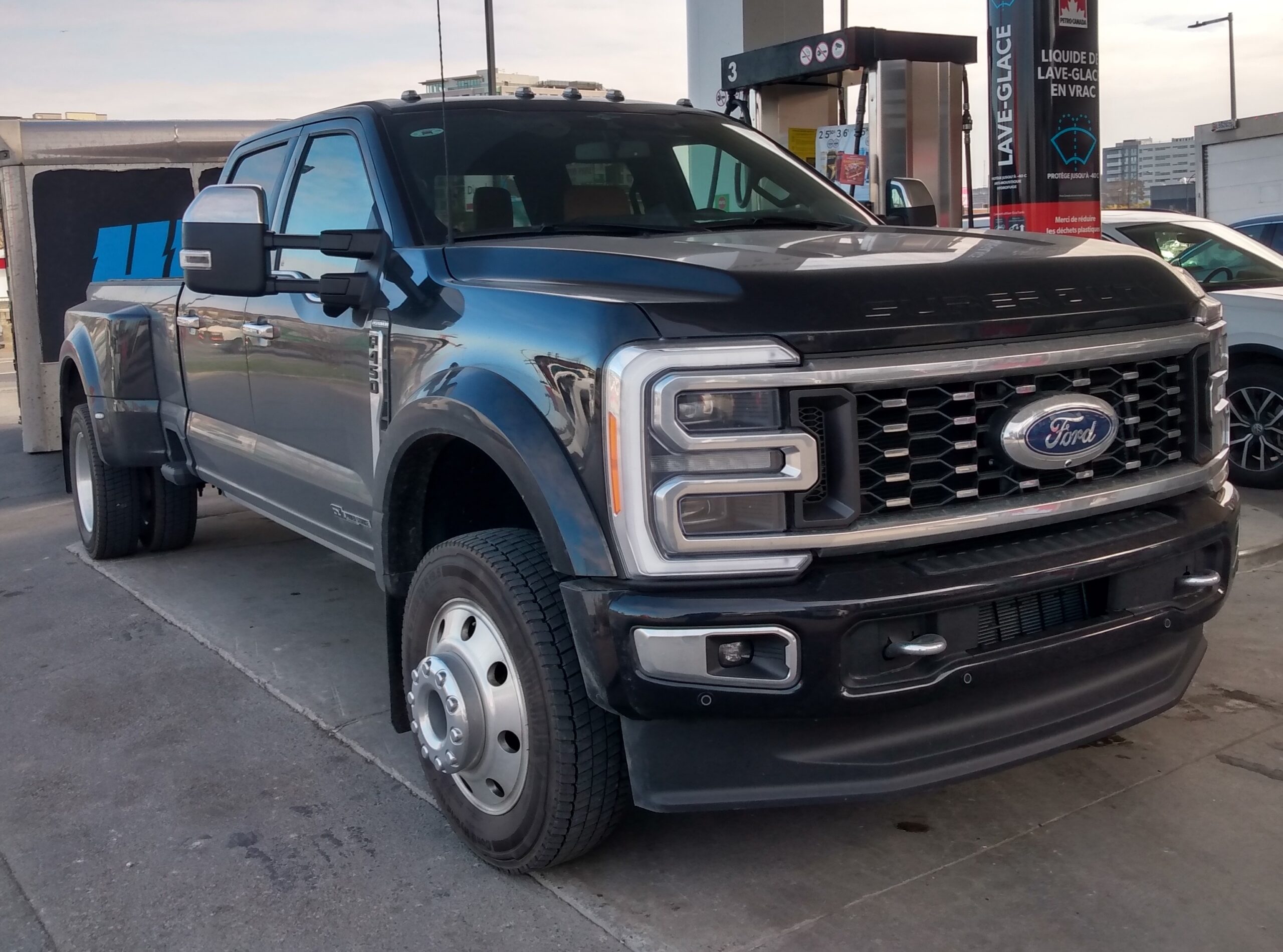
Ford F-450 Super Duty 2023 belongs to the P708 generation and uses a new fuse-box layout compared with the previous Super Duty generation. Ford divides the 12 V protection between the engine-compartment power-distribution box and the passenger-compartment fuse panel. Several under-hood positions have different ratings for gasoline and 6.7 Power Stroke diesel engines.
On chassis-cab or specialty-body vehicles, the body manufacturer may add separate fuses or breakers outside Ford’s factory boxes. The tables below cover the original Ford installation.
For another heavy-duty P708 configuration, see the F-350 Super Duty 2023. The lighter-duty sibling is the F-250 Super Duty 2023.
Fuse-box locations
Engine compartment: the high-current fuse box is under the hood, near the battery and service components. Passenger compartment: the interior fuse panel is on the passenger side behind the access panel in the side of the footwell.
Engine-compartment fuse box
Ford does not list every position number consecutively. The table below keeps exactly the positions present in the factory source, including repeated positions 24, 25 and 27 for gasoline and diesel ratings.
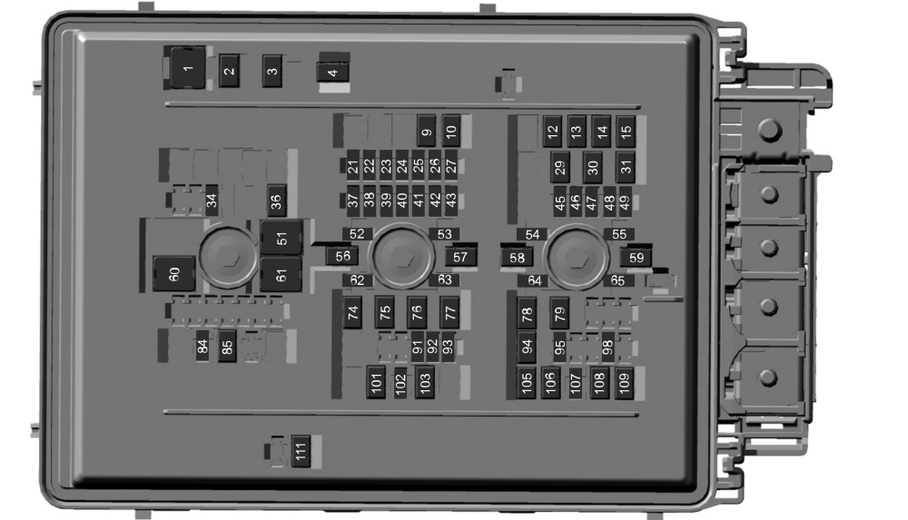
| Position | Rating [A] | Protected component / function |
|---|---|---|
| 1 | 50 | Cooling fan 1. |
| 2 | 50 | Heater. |
| 3 | 50 | Heater. |
| 4 | 50 | Heater. |
| 9 | 30 | 4×4 module. |
| 10 | 30 | CNG module switch – if equipped. |
| 12 | 60 | ABS pump. |
| 13 | 30 | Passenger power seat. |
| 14 | 40 | ABS valves. |
| 15 | 30 | Body Control Module (BCM) – RP2 bus. |
| 21 | 10 | Trailer reversing lamps. |
| 22 | 10 | 4×4 system. |
| 23 | 20 | Vehicle Power 1. |
| 24 | 20 | Vehicle Power 2 – gasoline engine. |
| 24 | 10 | Vehicle Power 2 – diesel engine. |
| 25 | 15 | Vehicle Power 3 – gasoline engine. |
| 25 | 10 | Vehicle Power 3 – diesel engine. |
| 26 | 20 | Vehicle Power 4. |
| 27 | 10 | Vehicle Power 5 – gasoline engine. |
| 27 | 20 | Vehicle Power 5 – diesel engine. |
| 29 | 15 | DEF tank heater – diesel. |
| 30 | 15 | DEF line heater – diesel. |
| 31 | 15 | Glow-plug and dosing module – diesel. |
| 34 | 20 | Rear heated seats. |
| 36 | 30 | Heated / ventilated seat module. |
| 37 | 5 | 24 V alternator – if equipped. |
| 38 | 10 | PCM, TCM. |
| 39 | 10 | ABS. |
| 40 | 10 | Electric power steering. |
| 41 | 10 | BLIS, trailer TPMS, rear CAN electronic module. |
| 42 | 10 | Snow plow – if equipped. |
| 43 | 15 | Run/Start feed for the passenger-compartment fuse panel. |
| 45 | 15 | Heated steering wheel. |
| 46 | 20 | Unused – spare. |
| 47 | 5 | Unused – spare. |
| 48 | 30 | Audio amplifier. |
| 49 | 25 | Unused – spare. |
| 51 | 40 | Blower motor. |
| 52 | – | Not used. |
| 53 | 10 | 4×4 transfer-case control module. |
| 54 | 10 | Unused – spare. |
| 55 | 10 | Unused – spare. |
| 56 | 40 | Electric power steering. |
| 57 | 20 | Trailer lighting module. |
| 58 | 50 | Customer Interface Module. |
| 59 | 60 | Power inverter. |
| 60 | 60 | B+ feed for the passenger-compartment fuse panel. |
| 61 | 30 | Vehicle battery 2. |
| 62 | 5 | Smart Trailer Hitch. |
| 63 | 10 | Smart Data Link Connector, Enhanced Central Gateway. |
| 64 | 5 | Glow-plug relay coil – diesel. |
| 65 | 10 | CNG module power – if equipped. |
| 74 | 30 | Trailer brake controller, auxiliary electric-brake access. |
| 75 | 30 | CNG constant power – if equipped. |
| 76 | 25 | Trailer lighting module battery-charge circuit. |
| 77 | 30 | Vehicle battery 1. |
| 78 | 20 | Power point 2. |
| 79 | 20 | Power point 1. |
| 84 | 20 | Horn. |
| 85 | 40 | Heated rear window. |
| 91 | 5 | Headlamp control module. |
| 92 | 15 | Left headlamp. |
| 93 | 15 | Right headlamp. |
| 94 | 20 | Power point 3. |
| 95 | 20 | Power point 4, Smart Charge module. |
| 98 | 10 | Tailgate release. |
| 101 | 50 | Customer Interface Module. |
| 102 | 5 | Rain sensor. |
| 103 | 30 | Front wiper motor. |
| 105 | 30 | Fuel pump. |
| 106 | 30 | Body Control Module (BCM) – RP1 bus. |
| 107 | 25 | Trailer parking lamps. |
| 108 | 40 | Driver power seat. |
| 109 | 30 | Starter. |
| 111 | 30 | Power sliding rear window. |
Passenger-compartment fuse panel
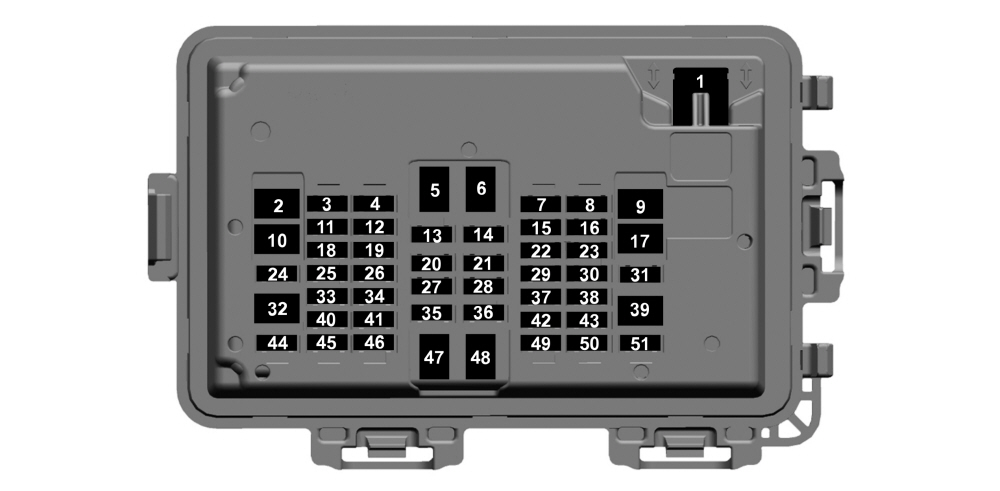
| Position | Rating [A] | Protected component / function |
|---|---|---|
| 1 | 30 | Power windows. |
| 2 | 30 | Power tailgate module. |
| 3 | 30 | Passenger door module. |
| 4 | 15 | Multi-contour seats. |
| 5 | – | Not used. |
| 6 | – | Not used. |
| 7 | 20 | Advanced driver-assistance systems module. |
| 8 | 10 | Delayed accessory-power logic. |
| 9 | – | Not used. |
| 10 | – | Not used. |
| 11 | 5 | Instrument cluster. |
| 12 | – | Not used. |
| 13 | 7.5 | Unused – spare. |
| 14 | 15 | SYNC. |
| 15 | 5 | Center high-mounted stop-lamp camera. |
| 16 | – | Not used. |
| 17 | – | Not used. |
| 18 | 10 | Radio transceiver module, 4×4 switch, Enhanced Central Gateway. |
| 19 | – | Not used. |
| 20 | 5 | Power inverter. |
| 21 | 5 | Upfitter / AUX switches. |
| 22 | 10 | Auxiliary camera. |
| 23 | – | Not used. |
| 24 | 30 | Moonroof. |
| 25 | 5 | Unused – spare. |
| 26 | 5 | Unused – spare. |
| 27 | 5 | Trailer brake-controller switch. |
| 28 | 5 | Electrochromic mirror. |
| 29 | 5 | Heating, ventilation and air-conditioning controls. |
| 30 | – | Not used. |
| 31 | – | Not used. |
| 32 | – | Not used. |
| 33 | 10 | Brake on/off switch. |
| 34 | 7.5 | Steering-column module, instrument cluster. |
| 35 | 5 | Rear heated seats. |
| 36 | 7.5 | Manual shift / SelectShift. |
| 37 | 5 | Head-Up Display. |
| 38 | 7.5 | Telematics module. |
| 39 | – | Not used. |
| 40 | 10 | Left-door switch, telescoping-mirror switch. |
| 41 | 10 | Adjustable pedals. |
| 42 | 5 | Central security module. |
| 43 | 5 | Headlamps, ignition switch. |
| 44 | 30 | Driver door module. |
| 45 | 7.5 | Wireless charger, driver front-seat module. |
| 46 | 20 | Radio. |
| 47 | – | Not used. |
| 48 | – | Not used. |
| 49 | 7.5 | SYNC display. |
| 50 | 5 | Additional Smart Data Link connector. |
| 51 | – | Not used. |
Factory AUX / Upfitter switches
Vehicles equipped with the six factory Upfitter switches have prepared auxiliary circuits routed to the engine compartment and passenger-side area. Each AUX circuit has its own fuse rating and wire color.
| Switch | Fuse [A] | Wire color | Function |
|---|---|---|---|
| AUX 1 | 10 | Purple / green | Auxiliary circuit 1. |
| AUX 2 | 15 | Green / brown | Auxiliary circuit 2. |
| AUX 3 | 15 | Yellow | Auxiliary circuit 3. |
| AUX 4 | 10 | Brown | Auxiliary circuit 4. |
| AUX 5 | 5 | Blue / orange | Auxiliary circuit 5. |
| AUX 6 | 5 | Yellow / orange | Auxiliary circuit 6. |
Important F-450 2023 circuits
Heavy towing circuits are deliberately separated: position 21 supplies trailer reversing lamps, 57 the trailer lighting module, 62 Smart Trailer Hitch, 74 the trailer brake controller, 76 the trailer-lighting-module charge circuit and 107 the trailer parking lamps. This separation helps narrow down a partial trailer-lighting or brake fault.
Gasoline vs diesel: positions 24, 25 and 27 use different fuse ratings depending on engine type. Diesel trucks also use positions 29, 30, 31 and 64 for DEF heaters and the glow-plug system.
Commonly checked circuits
- Fuel pump: engine position 105 – 30 A.
- ABS: positions 12 – 60 A, 14 – 40 A and 39 – 10 A.
- 4×4: positions 9 – 30 A, 22 – 10 A and 53 – 10 A.
- Trailer brake controller: engine position 74 – 30 A; cabin position 27 – 5 A supplies the controller switch.
- SYNC: cabin position 14 – 15 A; display position 49 – 7.5 A.
- Radio: cabin position 46 – 20 A.
- Upfitter switches: cabin position 21 – 5 A plus the separate AUX circuit fuses listed above.
FAQ – Ford F-450 Super Duty 2023 fuses
Why are some position numbers missing from the under-hood table?
Ford’s factory table does not enumerate every number. The article keeps only positions actually listed by the manufacturer instead of inventing missing positions as unused.
Why does position 24 have either 20 A or 10 A?
Position 24 is Vehicle Power 2. Ford specifies 20 A for gasoline engines and 10 A for the diesel. Positions 25 and 27 also vary by engine type.
Where is the trailer-brake controller fuse?
The main trailer-brake controller feed is engine-compartment position 74 – 30 A. The controller switch has a separate 5 A fuse at cabin position 27.
Do pickup and chassis-cab F-450s always have the same fuse population?
No. The base Super Duty architecture is shared, but installed options can change which positions are populated. A chassis-cab body builder may also add separate protection that is not part of Ford’s factory fuse boxes.