
Ford Fiesta Mk4 (1996-1999) uses a Central Junction Box (CJB) beneath the driver’s side dashboard and an additional Battery Junction Box (BJB) in the engine compartment. Petrol and 1.8 diesel engines, air conditioning, ABS, heated front windscreen and Scandinavian daytime running lights can alter fuse ratings and the fitted relay sockets. The 1999 facelift is often called Fiesta Mk5, although other catalogs continue to use Mk4 for both versions.
All 62 entries from the Polish source are preserved in four tables: 22 main cabin fuses, seven additional cabin positions, 20 engine-bay fuses including duplicate numbers with engine-specific ratings, and 13 under-bonnet relays/diodes. The four original illustrations are retained. Where a fuse number has two manufacturer-documented amp values, select the rating from the fuse legend for that specific vehicle, never the highest one automatically.
Where are the Ford Fiesta Mk4 fuse boxes?
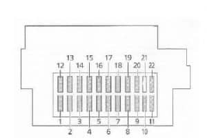
Inside the car: switch off the ignition and consumers, open the driver’s door and look below the steering wheel, behind the lower dash cover, for the Central Junction Box. Carefully release the trim fasteners and access the two-row, numbered 1-22 panel. Do not count fuse slots sequentially from one side without checking the physical diagram. Additional fuses and relays may sit behind or above the main CJB and are not always visible from the simple front opening.
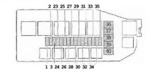
Engine compartment: with the engine and cooling fan stopped, open the bonnet and locate the supplementary BJB near the bulkhead. Release the cover retaining clips. This holder supplies headlamps, engine management, fuel pump or diesel fuel heating, ABS, cooling fans, heated windscreen and high-current cabin circuits. The relay holder is separate on some engines. Follow the manufacturer’s isolation procedure for 40-60 A fuses, and refit the protective cover securely.
Central Junction Box – positions 1-22
The front accessory socket / cigarette lighter is fuse F1 (15 A) in this documented configuration. F12 (20 A) supplies the front wipers, F16 (30 A) the cabin blower and F4 (20 A) the heated rear window. Factory heated seats, electric windows, mirror heating and alarm equipment require the corresponding options to be installed.
| Pozycja | Amperaż [A] | Chroniony obwód / funkcja |
|---|---|---|
| 1 | 15 | Cigarette lighter / 12 V accessory power socket |
| 2 | 7.5 | Interior courtesy lamps, clock and stored radio presets |
| 3 | 10 | Rear fog lamp and anti-theft alarm indicator |
| 4 | 20 | Heated rear window |
| 5 | 15 | Horn and hazard warning system |
| 6 | 7.5 | Left front position lamp |
| 7 | 7.5 | Right front position lamp |
| 8 | 15 | Electronic control module supply, including selected central-locking equipment |
| 9 | 25 | Headlamp switch battery feed |
| 10 | 15 | Heated front seats, if fitted |
| 11 | 30 | Central door locking and electric windows |
| 12 | 20 | Front windscreen wiper motor and washer pump |
| 13 | 15 | Brake lights and instrument cluster |
| 14 | 10 | SRS airbag control system |
| 15 | 7.5 | Heated exterior rear-view mirrors |
| 16 | 30 | Heating and ventilation blower motor |
| 17 | 15 | Turn indicators |
| 18 | 15 | Engine-bay circuits and electronic control unit supply |
| 19 | 7.5 | Engine management, car radio and auxiliary relay |
| 20 | 20 | Ignition feed to main lighting switch |
| 21 | 15 | Central locking and electrically adjustable door mirrors |
| 22 | 10 | On-board diagnostics connector and radio on specific versions |
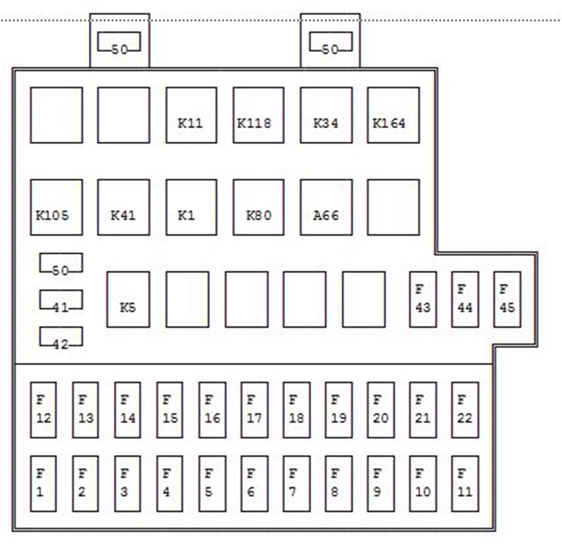
Additional central junction fuses F41-F50
These positions can protect supplementary rear fog lamp, central locking, tailgate release and lighting equipment. F43 (10 A) covers the Daytime Running Lights installation on Scandinavian-market cars and need not be fitted on other versions. The positions F46-F48 are not specified in the original table and are not assigned hypothetical functions. The general CJB overview shows the carrier layout; it is not a dedicated map of every auxiliary slot.
| Pozycja | Amperaż [A] | Chroniony obwód / funkcja |
|---|---|---|
| 41 | 10 | F41 – rear fog lamp, depending on installed wiring |
| 42 | 10 | F42 – rear fog lamp, alternate equipment/wiring version |
| 43 | 10 | F43 – daytime running lamp equipment for Scandinavian markets |
| 44 | 20 | F44 – central door locking |
| 45 | 15 | F45 – electric tailgate/boot release |
| 49 | 20 | F49 – dipped and main-beam headlamp auxiliary feed, depending on equipment |
| 50 | 25 | F50 – position lamps and main lighting switch additional supply |
Engine compartment BJB – fuses F23-F40
F23/F24 (10 A each) supply left and right high beams; F25/F26 (10 A each) protect left and right dipped headlights. Petrol and diesel engines differ at F27: petrol lambda oxygen sensor 10 A, diesel 1.8 fuel heater 15 A. F34 can be 30 A for PCM control on one factory configuration, or 25 A for petrol octane coding on a different European installation.
F35 (10 A) concerns the petrol fuel pump and related relay, while some 1.8 diesel layouts use this number for PATS immobiliser equipment instead. The archived Mk4 source does not specify a confirmed diesel 3 A variant here; it is therefore not copied from the later 1999-2002 Fiesta Mk5. F36-F40 include 40-60 A main supplies and must be checked against the installed engine and fuse box before replacing.
| Pozycja | Amperaż [A] | Chroniony obwód / funkcja |
|---|---|---|
| 23 | 10 | F23 – left high-beam headlamp |
| 24 | 10 | F24 – right high-beam headlamp |
| 25 | 10 | F25 – left dipped-beam headlamp |
| 26 | 10 | F26 – right dipped-beam headlamp |
| 27 | 10 | F27 – petrol engine oxygen/lambda sensor |
| 27 | 15 | F27 – diesel 1.8 fuel preheater, alternate position |
| 28 | 15 | F28 – engine management PCM and related sensors, injectors, fuel pump relay, idle control and emissions equipment according to engine |
| 29 | 20 | F29 – air conditioning and front fog lamps, A/C pressure switch |
| 30 | 3 | F30 – ABS electronic control circuit |
| 31 | 30 | F31 – ABS hydraulic/controller main supply |
| 32 | 3 | F32 – engine PCM keep-alive memory feed |
| 33 | 30 | F33 – ABS, or radiator cooling fan on models without ABS and air conditioning |
| 34 | 30 | F34 – engine PCM supply, factory 30 A version |
| 34 | 25 | F34 – petrol octane coding/adjustment circuit, alternative European 25 A version |
| 35 | 10 | F35 – petrol fuel pump relay feed or diesel PATS anti-theft system, engine-specific |
| 36 | 60 | F36 – cooling fan, engine management and starting; diesel preheating related supply |
| 37 | 40 | F37 – heated front windscreen |
| 38 | 60 | F38 – main ignition relay/electrical supply, equipment-dependent |
| 39 | 60 | F39 – interior distribution; Scandinavian DRL versions may use it for lighting supply |
| 40 | 60 | F40 – ignition switch and main central fuse board supply |
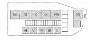
Engine compartment relays K4-K158 and diode V33
The relay codes identify individual circuits for petrol fuel pump, engine management, starter, air conditioning, headlamps, radiator fans and diesel glow-plug preheating. For example K70 is only applicable on the diesel 1.8, and K26 or K158 need not be installed on cars without fog lamps or air conditioning. V33 is a diode associated with the main relay, not a current-rated fuse.
| Pozycja | Amperaż [A] | Chroniony obwód / funkcja |
|---|---|---|
| K4 | – | K4 – fuel pump relay on petrol engines |
| K13 | – | K13 – main power hold-on relay for engine management |
| K22 | – | K22 – starter motor relay |
| K26 | – | K26 – front fog lamp relay |
| K32 | – | K32 – A/C cut-out relay at wide-open throttle |
| K36 | – | K36 – dipped-beam headlamp relay |
| K37 | – | K37 – high-beam headlamp relay |
| K45 | – | K45 – engine cooling fan relay |
| K46 | – | K46 – high-speed engine cooling fan relay |
| K70 | – | K70 – glow plug preheating relay on 1.8 diesel |
| K157 | – | K157 – supplementary equipment relay |
| K158 | – | K158 – air-conditioning relay |
| V33 | – | V33 – main electrical relay diode, not a fuse |
Changes during 1997-1999 and the later Fiesta facelift
The Fiesta range went through wiring harness revisions during 1997 and a facelift in 1999. Some British, continental European and Scandinavian cars have different daylight running light or fog lamp modules. The manufactured date and actual CJB/BJB markings are a better identification than the registration year alone. The next facelift can be found in the Ford Fiesta Mk5 (1999-2002) fuse and relay diagrams; do not interchange the optional F41-F50 assignments without confirming the box.
Typical Fiesta Mk4 electrical faults
No power at the 12 V socket: inspect cabin F1 (15 A), then remove any charger and check the socket for loose metal or damaged wiring. Front wiper failure: inspect cabin F12 (20 A), motor, switch and linkage. Heated rear window inoperative: check F4 (20 A), the relay and heating element terminals.
No fuel pump noise on a petrol engine: inspect BJB F35 (10 A), the K4 fuel pump relay and fuel pump supply. On the 1.8 diesel, F27 (15 A) supplies fuel heating and K70 controls glow plugs instead. One headlamp failed: first check its separate F23-F26 (10 A) fuse, then bulb and connector.
ABS warning lamp: check F30 (3 A), F31 (30 A) and the correct engine-specific F33 supply, then retrieve the stored fault code. Cabin electrics stop together: check F38-F40 power distribution, battery terminals and the main earth connections, rather than raising the fuse rating.