
Ford Puma I (1997-2002) is the compact coupe based on the Ford Fiesta Mk4 platform, not the later Ford Puma crossover introduced in 2019. The first-generation car has a fuse carrier beneath the driver’s dashboard and another near the battery in the engine compartment. Its fuse and relay layouts changed around September 1999 and July 2000, so it is important to identify the version fitted to the car.
Three complete tables below contain 103 actual fuse, relay and diode entries, preserving alternative ratings for the same numbered slot, unoccupied positions and model-year differences. The older and newer under-bonnet diagrams are not interchangeable. The year of first registration is less reliable than the actual build date and the fuse carrier present in the vehicle.
Where are the Ford Puma I fuse boxes?
Passenger compartment: switch off the ignition and all electrical consumers. Open the driver’s door and locate the lower dashboard service cover close to the A-pillar and steering column. Depending on production date, release the retaining clip or folding latch, lower the panel and inspect the fuse layout on its underside. Right-hand-drive cars can have a different access arrangement.
Engine compartment: open the bonnet and find the covered black power distribution box near the battery. Release its plastic clips and compare the installed carrier with the early and late diagrams below before removing a fuse. For the 40-60 A high-current links, follow the manufacturer’s isolation procedure; do not bridge them or increase their ratings.
Passenger compartment fuse carrier – 1997 to 2002
Five original diagrams show cabin configurations before September 1999, those in the 1999-2000 transition with and without double locking, and the later versions with and without central locking. The table keeps both documented F2, F19 and F42 amp ratings. K codes refer to relays; A66 is the lights-on warning buzzer.

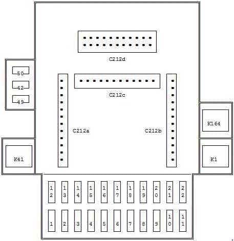
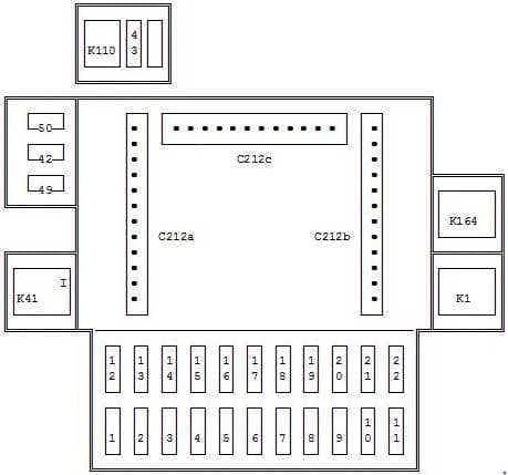
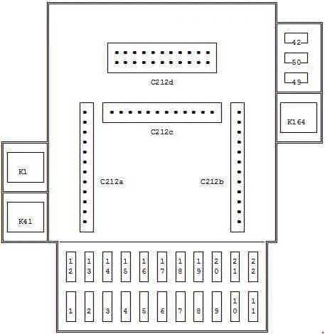
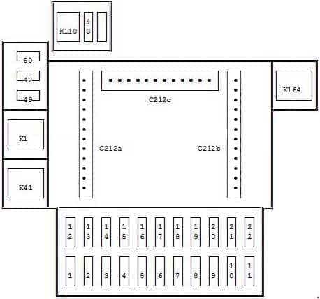
| Pozycja | Amperaż [A] | Chroniony obwód / funkcja |
|---|---|---|
| 1 | 15 | Cigarette lighter and 12 V accessory socket |
| 2 | 7.5 | From September 1999: interior lighting and clock |
| 2 | 10 | Up to July 1999: radio and interior lighting, alternate fuse assignment |
| 3 | 10 | From September 1999: Generic Electronic Module (GEM) for body functions |
| 4 | 20 | Heated rear window |
| 5 | 15 | Hazard warning lights and horn |
| 6 | 7.5 | Left parking lamps and instrument illumination, equipment-dependent |
| 7 | 7.5 | Right parking lamps and registration plate lighting |
| 8 | 15 | Central locking and exterior electric mirror adjustment |
| 9 | 15 | Electric seat adjustment, where installed |
| 10 | – | Unoccupied socket on this fuse card |
| 11 | 30 | Electric window motors |
| 12 | 20 | Front windscreen wiper motor |
| 13 | 15 | Heater/ventilation and stop or reversing lamps, depending on equipment |
| 14 | 10 | Supplemental Restraint System (SRS) airbag controller |
| 15 | 20 | From September 1999 heated mirrors; earlier cars can use this position for daytime running lights (DRL) |
| 16 | 30 | Heater and ventilation blower motor |
| 17 | 15 | Direction indicators |
| 18 | 15 | Engine ECU / Powertrain Control Module (PCM) |
| 19 | 7.5 | From September 1999: ignition-controlled terminal 75 |
| 19 | 10 | Up to July 1999: terminal 75 ignition feed, alternate rating |
| 20 | 20 | Up to July 1999: heated exterior mirrors |
| 21 | 25 | Up to July 1999: side and position lighting |
| 22 | 10 | From September 1999 radio supply; from July 2000 also diagnostic connector |
| 42 | 15 | From September 1999: GEM body control module |
| 42 | 10 | Up to July 1999: rear fog lamp, alternate use of position 42 |
| 43 | 10 | From September 1999: electric tailgate release |
| 44 | 20 | Up to July 1999: central locking |
| 49 | 20 | From September 1999: daytime running lights |
| 50 | 25 | From September 1999: side lights |
| K1 | – | Heated rear window relay |
| K11 | – | Up to July 1999: front wiper motor relay |
| K41 | – | Ignition relay |
| K43 | – | Up to July 1999: left direction-indicator relay |
| K44 | – | Up to July 1999: right direction-indicator relay |
| K110 | – | Electric boot/tailgate release relay |
| K118 | – | Up to July 1999: interior lighting relay |
| K164 | – | From September 1999 wiper relay; earlier installations use the headlamp washer circuit |
| A66 | – | Warning buzzer for lamps left on |
Engine fuse and relay box – before July 2000
In the earlier box F23-F26 protect left and right high and dipped headlamps in sequence. Other positions include PCM, fuel pump, cooling, ABS and air conditioning. K4, K13, K32, K36, K37, K45, K46, K94, K157 and K158 are retained together with diode V33.
F34 is labelled octane adjustment in an older chart, but the precise function should not be assumed for every engine and market. The small original image is retained, with a scalable text-based slot index as a reading aid.
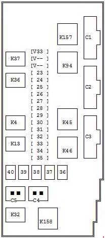
| Pozycja | Amperaż [A] | Chroniony obwód / funkcja |
|---|---|---|
| 23 | 10 | Left main-beam headlamp |
| 24 | 10 | Right main-beam headlamp |
| 25 | 10 | Left dipped-beam headlamp |
| 26 | 10 | Right dipped-beam headlamp |
| 27 | 10 | Heated exhaust oxygen sensor (HEGO) |
| 28 | 15 | Electronic Powertrain Control Module (PCM) supply |
| 29 | 20 | Reversing lights and air conditioning circuits |
| 30 | 3 | ABS low-current supply |
| 31 | 30 | ABS main supply circuit one |
| 32 | 3 | PCM keep-alive memory feed |
| 33 | 30 | ABS main supply circuit two |
| 34 | 30 | Legacy chart labels this as octane adjustment; exact use must be verified against the vehicle wiring and engine |
| 35 | 10 | Fuel pump |
| 36 | 60 | Starter and engine cooling fan main supply |
| 37 | 40 | Optional audio amplifier and headlamp washers |
| 38 | 60 | Ignition relay high-current supply |
| 39 | 60 | Main vehicle electrical distribution |
| 40 | 60 | Passenger compartment junction box and ignition switch supply |
| K4 | – | Fuel pump relay |
| K13 | – | Power-hold relay |
| K94 | – | Starter inhibit relay |
| K32 | – | Air conditioning relay |
| K36 | – | Dipped-beam relay |
| K37 | – | Main-beam relay |
| K45 | – | Engine cooling fan relay |
| K46 | – | High-speed engine cooling fan relay |
| K157 | – | Accessory equipment relay |
| K158 | – | Air conditioning controller relay |
| V33 | – | Power-hold circuit diode |
Engine compartment fuse box – from July 2000
The later box moves ABS protection to F24, F26 and F28 and the dipped beams to F27 (left) and F29 (right). New 51-56 high-current positions provide major power feeds. Vacant positions F35, F37, F38 and F54 are shown, as are all relays K4-K244 and diodes V22 and V33. Cars built during 2000 require physical identification of the installed box.
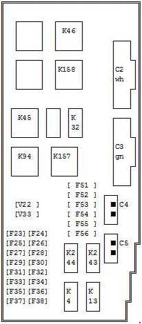
| Pozycja | Amperaż [A] | Chroniony obwód / funkcja |
|---|---|---|
| 23 | 10 | Left main-beam headlamp |
| 24 | 30 | ABS power circuit one |
| 25 | 10 | Right main-beam headlamp |
| 26 | 10 | ABS power circuit two |
| 27 | 10 | Left dipped-beam headlamp |
| 28 | 3 | ABS low-current third circuit |
| 29 | 10 | Right dipped-beam headlamp |
| 30 | 15 | Powertrain Control Module (PCM) |
| 31 | 10 | Fuel pump |
| 32 | 20 | Air conditioning compressor and controls |
| 33 | 3 | PCM keep-alive memory supply |
| 34 | 30 | Until September 2000 the older listing labels this octane adjustment; confirm exact function in vehicle wiring |
| 35 | – | Unoccupied position |
| 36 | 10 | Heated exhaust oxygen sensor (HEGO) |
| 37 | – | Unoccupied position |
| 38 | – | Unoccupied position |
| 51 | 60 | Starter and radiator fan main supply |
| 52 | 40 | Headlamp washer system, if equipped |
| 53 | 60 | Ignition relay high-current supply |
| 54 | – | Unoccupied position |
| 55 | 60 | Main electrical distribution power |
| 56 | 60 | Passenger compartment fuse carrier and ignition switch power |
| K4 | – | Fuel pump relay |
| K13 | – | Power-hold relay |
| K26 | – | Front fog light relay |
| K32 | – | Air conditioning relay |
| K45 | – | Engine cooling fan relay |
| K46 | – | High-speed cooling fan relay |
| K94 | – | Starter inhibit relay |
| K157 | – | Accessory relay |
| K158 | – | Air conditioning relay |
| K243 | – | Dipped-beam headlamp relay |
| K244 | – | Main-beam headlamp relay |
| V22 | – | Cooling fan relay diode |
| V33 | – | Power-hold circuit diode |
Production date, engine and equipment differences
The GEM body electronics module, central locking, wiper relays, lighting circuits and engine compartment fuse carrier changed during the model’s life. Options such as air conditioning, headlamp washers, daytime running lights and electric seat adjustment were not fitted to every Puma.
The petrol 1.4, 1.6 and 1.7 engines may use different ECU and auxiliary relay wiring. The fuse legend fitted to the individual vehicle takes priority over a general table; do not transfer any of these allocations to a second-generation Puma crossover.
Common electrical faults on the Ford Puma I
12 V cigarette lighter not working: check cabin F1 (15 A) and the socket itself, especially for metal objects or an accessory short. Electric windows stopped: cabin F11 (30 A); inspect the door wiring and switches if only one side fails.
Cabin fan has no power: inspect F16 (30 A), then the blower motor and its resistor. Stop lamps or horn failed: examine the relevant F13 or F5 (both 15 A) and the actual switches and connectors.
One dipped beam not working: the older engine box uses F25 for left and F26 for right; the later box uses F27 for left and F29 for right. All are 10 A on the documented configurations. Check the bulb and plug as well.
Engine will not start: after battery and ground tests, check the appropriate fuel pump fuse and K4 relay and the installed PCM feeds. ABS warning: older cars have F30-F33-related protection, while later cars use F24, F26 and F28. If intact, diagnostic trouble codes and hydraulic wiring checks are needed.
Another English Ford fuse guide for a substantially different electrical generation is Ford S-Max Mk1. The fuse numbers of the two vehicles must never be mixed.