
Mazda 2 DE/DH (2007-2014), the second-generation Mazda2, uses an engine-bay fuse and relay carrier and a smaller fuse panel in the passenger compartment. The 40 under-bonnet positions and 16 cabin positions are shown separately below, including unpopulated slots and options fitted only to certain markets, engines or trims.
This guide preserves all 56 original fuse positions of the Polish article. The layout applies to the illustrated DE/DH fuse carrier, but Mazda changed engine management and optional equipment circuits during production. The label under the original fuse-box cover and the handbook for the vehicle’s market are the correct references before fitting a replacement of a particular amp rating.
Where are the Mazda 2 DE/DH fuse boxes?
Engine compartment: park safely, switch off the ignition and wait for the cooling fan to stop. Open the bonnet and find the large, black covered fuse box close to the battery. Press the cover retaining clips, lift the lid and match the numbered drawing with the panel inside. Major ignition supply fuses IG KEY 1 (40 A) and IG KEY 2 (30 A) are not ordinary accessory feeds; follow the manufacturer’s battery isolation instructions when checking bolted or high-current links.
Passenger compartment: on a left-hand-drive Mazda2, open the driver’s door and look at the lower side of the dashboard by the footwell, behind the removable trim cover. Open the cover carefully, locate the numbered cabin positions and use insulated fuse pullers for suitable blade fuses. Access can differ on right-hand-drive models. Refit the cover securely to prevent accidental contact with the wiring.
Engine compartment fuse carrier – all 40 positions
The under-bonnet box protects fuel pump, injection, headlights, the central door locking system, ABS/DSC stability electronics, cooling fan and cabin blower. The empty positions are deliberately included: an unused FAN1, FAN3, GLOW or ENG INJ2 cavity on this fuse card must not be filled merely because a similarly named component exists in another Mazda2 variant.
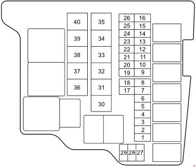
| Pozycja | Amperaż [A] | Chroniony obwód / funkcja |
|---|---|---|
| 1 | – | FUEL HEAT – unused on this equipment configuration; other fuel system variants use this position |
| 2 | 15 | FUEL PUMP – fuel pump electrical supply |
| 3 | 15 | F.FOG – front fog lamps, if fitted |
| 4 | 20 | P/W – electric power windows main branch |
| 5 | 10 | HORN – horn |
| 6 | 10 | EGI – electronic engine management and fuel injection |
| 7 | 30 | DSC-P – Dynamic Stability Control hydraulic pump supply |
| 8 | 20 | DSC-V – Dynamic Stability Control solenoid valve supply |
| 9 | 7.5 | MAG – air-conditioning compressor electromagnetic clutch |
| 10 | 15 | TAIL – tail lamps, position lamps and number plate lighting |
| 11 | 10 | STOP – brake and stop lamps |
| 12 | 7.5 | SWS – Supplemental Restraint System (SRS) airbag supply as identified in this original fuse chart |
| 13 | 20 | R.DEF – heated rear window |
| 14 | 10 | HAZARD – direction indicators and hazard flashers |
| 15 | 20 | D/L – central door locking |
| 16 | – | EOP – unused in this equipment variant |
| 17 | 15 | ENG BAR – engine control electrical circuit |
| 18 | 15 | ENG INJ – fuel injection and engine controller |
| 19 | – | ENG INJ2 – unused additional engine injection position |
| 20 | – | H/L HI RH – right high-beam headlamp provision, unoccupied in this arrangement |
| 21 | – | H/L HI LH – left high-beam headlamp provision, unoccupied in this arrangement |
| 22 | – | DCDC3 – unused DC-DC converter position |
| 23 | 15 | H/L LO RH – right dipped-beam headlamp |
| 24 | 15 | H/L LO LH – left dipped-beam headlamp |
| 25 | – | AUDIO2 – vacant auxiliary audio position |
| 26 | – | DSC-V2 – vacant second DSC valve position |
| 27 | – | HORN2 – vacant additional horn circuit |
| 28 | – | METER – unoccupied instrument cluster position |
| 29 | 15 | ROOM – interior courtesy and roof lighting |
| 30 | – | GLOW – unused diesel preheating provision on this engine/equipment arrangement |
| 31 | – | EWT – vacant provision in the factory diagram |
| 32 | 40 | IG KEY 1 – high-current ignition-switched feed number 1 |
| 33 | – | FAN 3 – unoccupied supplementary cooling-fan circuit |
| 34 | 30 | FAN 2 – engine radiator cooling fan motor |
| 35 | – | FAN 1 – unoccupied cooling-fan position |
| 36 | – | INJ – vacant additional fuel injection supply |
| 37 | 30 | IG KEY 2 – high-current ignition-switched feed number 2 |
| 38 | – | 4WD – unoccupied all-wheel-drive provision |
| 39 | – | ABS DSC-P2 – unused additional ABS/DSC pump protection |
| 40 | 30 | BLOWER – cabin heating and air-conditioning blower motor |
Passenger compartment fuse box – all 16 positions
The cabin panel includes the most common consumer circuits: CIGAR position 3 (15 A) for the accessory 12 V socket, F.WIP position 8 (20 A) for the front wipers, R.WIP position 9 (10 A) for the rear wiper, MIRROR position 4 (7.5 A) for electric mirror adjustment and P/W position 16 (30 A) for windows.
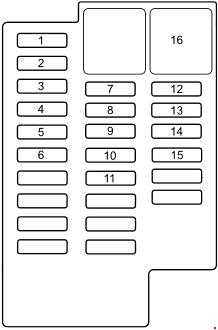
| Pozycja | Amperaż [A] | Chroniony obwód / funkcja |
|---|---|---|
| 1 | – | TCM – automatic transmission control module provision, unoccupied here |
| 2 | 7.5 | ILLUMI – instrument panel and switch illumination |
| 3 | 15 | CIGAR – cigarette lighter and 12 V accessory socket |
| 4 | 7.5 | MIRROR – electric adjustment of the exterior mirrors |
| 5 | 7.5 | M.DEF – heated outside mirror glass |
| 6 | – | S.WARM – unoccupied auxiliary warming circuit |
| 7 | 7.5 | A/C – air-conditioning control electronics |
| 8 | 20 | F.WIP – front windscreen wiper and washer |
| 9 | 10 | R.WIP – rear window wiper and washer |
| 10 | – | STARTER – unoccupied starter relay supply position |
| 11 | – | METER 2 – unoccupied supplementary instrument circuit |
| 12 | 10 | ENG – engine control electronics |
| 13 | 10 | METER – instrument cluster and gauges |
| 14 | 10 | SAS – airbag / supplemental restraint safety system |
| 15 | – | AUDIO 3 – unoccupied supplementary audio circuit |
| 16 | 30 | P/W – electric power windows |
Petrol, diesel and optional equipment differences
Diesel-specific glow or fuel-heater protection may use positions that are vacant on the illustrated petrol-oriented arrangement. DSC-P (30 A) and DSC-V (20 A) are fitted only to vehicles with the corresponding stability-control system. Further differences can affect DC-DC, automatic transmission and headlamp high-beam circuits. Compare the printed fuse identification and engine code with the installed vehicle.
Different Mazda2 markets can have alternative fuse numbering even within the same body generation; do not substitute a fuse card from a newer Mazda2 DJ or the related Ford Fiesta solely because the models share some engineering.
Common Mazda 2 DE/DH electrical faults
12 V socket stopped working: check cabin CIGAR number 3 (15 A). Inspect the socket and removable charger for a short if the replacement fuse immediately fails. Front wipers stopped: check cabin F.WIP number 8 (20 A), followed by the wiper linkage and motor. The rear wiper has its own R.WIP number 9 (10 A).
Cabin blower does not operate: inspect under-bonnet BLOWER number 40 (30 A), then the motor and fan speed controller. One dipped beam failed: the right lamp uses H/L LO RH number 23 (15 A) and the left H/L LO LH number 24 (15 A) in this version. Check bulb, connector and earth before replacing other parts.
Electric windows failed: the engine carrier P/W number 4 (20 A) and cabin P/W number 16 (30 A) are separate supplies. If one window fails, inspect its switch, regulator and the wiring in the door aperture. Central door locking failed: check under-bonnet D/L number 15 (20 A), then investigate locks and wiring.
DSC/ABS warning illuminated: check DSC-P number 7 (30 A) and DSC-V number 8 (20 A) only if the particular vehicle is fitted with those modules. An intact fuse does not exclude a faulty wheel-speed sensor or control module.
For more Mazda models and years, browse the English Mazda fuse box guides. The exact DE/DH diagrams in this article do not apply to every Mazda2 generation.