
The 2016 Nissan Pulsar C13 is the European five-door hatchback, not the earlier Pulsar N15 or the Australian-market B17 sedan. Its electrical equipment includes a dashboard-side fuse panel and at least two fuse / relay modules in the engine compartment. The arrangement can change with engine, market and equipment level.
This guide covers the documented 2016 configuration, including alternative current ratings. A dash in a fuse-rating cell means the source did not provide one universal rating for that multi-fuse link; it does not permit fitting an arbitrary substitute. Check the legend on the installed fuse box and the vehicle manual.
Contents
Where are the fuse boxes in the Nissan Pulsar C13?
Passenger compartment: switch the ignition off and open the driver’s door. Remove the plastic end panel on the side of the dashboard to expose the fuse carrier. The fuse puller is normally stored in or on the fuse box. Note the position and colour of the original fuse, then replace it only with the specified rating.
Engine compartment: open the bonnet and locate the covered distribution modules close to the battery. Release the cover clips and examine the diagram inside. High-current cartridge fuses and fusible links may also be fitted; additional main fusible links can be integrated into the positive battery connection. These should be dealt with according to the manufacturer’s service procedure, not pulled out with the circuit live.
Passenger-compartment fuse box – Nissan Pulsar 2016
Position 1 is listed in 15 A and 20 A alternatives. Positions 11, 12 and 13 also have equipment-dependent assignments or ratings. These are alternatives, not instructions to fit two fuses in one socket. The 2016 reference does not identify position 2, so no circuit has been invented for it. The dashboard panel serves the 12 V socket, ventilation, audio, cabin equipment and restraint systems.
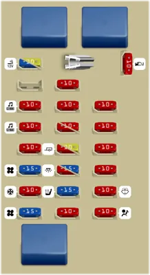
| Pozycja | Amperaż [A] | Chroniony obwód / funkcja |
|---|---|---|
| 1 | 15 | 12 V accessory socket / cigarette lighter – equipment-dependent rating |
| 1 | 20 | 12 V accessory socket / cigarette lighter – alternative rating; verify the vehicle’s label before replacement |
| 3 | 10 | Audio system and electric door mirrors, AUDIO/MIRROR 1 |
| 4 | 10 | Audio system and electric door mirrors, AUDIO/MIRROR 2 |
| 5 | 10 | Intelligent Power Distribution Module (IPDM), ignition circuit IG2 |
| 6 | 15 | Heater and ventilation blower motor – circuit 1 |
| 7 | 10 | Air-conditioning control unit |
| 8 | 15 | Heater and ventilation blower motor – circuit 2 |
| 9 | 10 | Passenger-compartment electrical accessories |
| 10 | 10 | Anti-theft system |
| 11 | 10 | Electrical accessories – equipment-dependent assignment |
| 11 | 10 | Instrument cluster – alternative assignment for position 11 |
| 12 | 10 | Dealer-installed optional accessories |
| 12 | 20 | Trailer wiring – alternative use of position 12 |
| 13 | 10 | Interior lighting – one installation variant |
| 13 | 15 | Interior lighting – alternative rated fuse |
| 14 | 15 | Heated front seats |
| 15 | 10 | Engine start button |
| 16 | 10 | Additional passenger-compartment electrical accessories |
| 17 | 10 | Instrument cluster, ignition-switched feed |
| 18 | 10 | Ignition-switched electrical accessories – circuit 2 |
| 19 | 10 | Ignition-switched electrical accessories – circuit 1 |
| 20 | 10 | Windscreen washer pump |
| 21 | 10 | SRS airbag control unit |
| 22 | 10 | Heated exterior mirrors |
Engine compartment – fuse and relay block 1
This module contains the diesel fuel heater, electric PTC supplementary heaters, door locking, VDC / ABS supply, power steering, the radiator fan and horn relay R1. Multi-fuse (MPF) assemblies require the correct vehicle-specific part rather than a generic blade-fuse substitute.
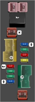
| Pozycja | Amperaż [A] | Chroniony obwód / funkcja |
|---|---|---|
| 2 | 40 | Main ignition switch supply (IGN SW) – check the fitted fusible-link variant |
| 3 | 40 | Power windows, main feed (P/WDW) |
| 4 | 40 | Vehicle Dynamic Control (VDC) motor supply |
| 5 | 20 | Diesel fuel heater |
| 6 | 10 | Anti-theft protection circuit |
| 7 | 30 | Additional electric PTC heater – stage 3 |
| 8 | 15 | Power door locking – secondary circuit |
| 9 | 15 | Power door locking – main circuit |
| 10 | 30 | Additional electric PTC heater – stage 2 |
| 11 | 30 | Additional electric PTC heater – stage 1 |
| 12 | 10 | Horn |
| 13 | 60 | Electric power steering (EPS), main supply |
| 14 | 30 | Headlamp washers, where fitted |
| 15 | 30 | Vehicle Dynamic Control (VDC), valves and controller |
| 16 | 50 | Radiator cooling fan supply |
| 17 | 30 | 400 W DC/DC converter – first circuit |
| 18 | 30 | 400 W DC/DC converter – second circuit |
| R1 | – | Horn relay |
Engine compartment – fuse and relay block 2
The second documented block covers optional Bose audio, CVT transmission control, daytime running lamps, brake lights and the main ABS / VDC, cooling-fan and steering circuits. Lettered positions G-N can contain high-current links. Where the exact rating is not established, consult the fitted fuse carrier before any replacement.
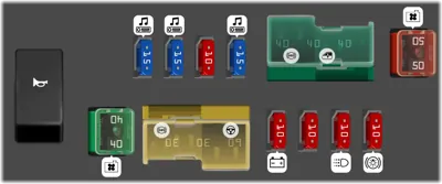
| Pozycja | Amperaż [A] | Chroniony obwód / funkcja |
|---|---|---|
| 24 | 15 | Factory Bose audio system – first supply |
| 25 | 15 | Factory Bose audio system – second supply |
| 26 | 10 | Continuously Variable Transmission (CVT) controller |
| 27 | 15 | Audio system |
| 28 | 10 | Horn and alternator charging circuit |
| 29 | 10 | CVT transmission control – second circuit |
| 30 | 10 | Daytime running lights (DRL) |
| 31 | 10 | Brake lights (STOP) |
| G | – | Main ABS / VDC supply; fusible-link rating depends on the fitted module |
| H | – | Power-window fusible link; check the module marking |
| I | – | Main ignition switch power supply |
| J | 50 | Radiator cooling fan – first supply |
| K | 40 | Radiator cooling fan – second supply |
| L | – | Additional ABS / VDC circuit; check the housing marking |
| M | – | Spare position on certain configurations |
| N | – | Electric power steering (EPS) supply |
| R5 | – | Horn relay |
Differences between engines, transmissions and trim levels
1.5 dCi diesel: the fuel heater and three-stage PTC cabin heater are diesel-specific circuits. Do not assume those fuses will be installed in a 1.2 DIG-T petrol model.
CVT versus manual transmission: in CVT-equipped cars, block 2 positions 26 and 29 supply transmission-control circuits. Some manual models do not populate these circuits.
Bose audio, heated seats and headlamp washers: the optional equipment determines which fuse locations are fitted. An empty Bose position in a car with standard audio is not evidence of a fault.
Practical fault checks for a 2016 Pulsar
The 12 V socket is dead: inspect cabin position 1, but determine whether your vehicle uses the 15 A or 20 A version from the installed fuse-box legend. Never upgrade the fuse merely because an alternative diagram lists a higher value.
The heater blower does not run: check cabin positions 6 and 8 (both 15 A in this chart). If both fuses are intact, test the blower motor, resistor / speed controller and associated connections.
Electric windows have stopped working: inspect the main P/WDW feed in engine block 1, then check the window switches and wiring between the door and body.
The diesel cabin warms slowly: inspect the PTC heater stages 1-3 without confusing their protection with the diesel glow-plug circuit. Work on high-current protection should follow the vehicle service instructions.
The horn is silent: inspect engine block 1 position 12 (10 A) and relay R1. Another documented module labels a horn relay R5; check which actual layout is fitted.
An ABS / VDC warning remains lit: confirm supply to the correct control unit before reading diagnostic fault codes and testing wheel-speed sensors.
Fuse locations from a different Pulsar generation or the Nissan Note are not interchangeable. For other Nissan guides published in English, browse the Nissan fuse box diagrams section.