
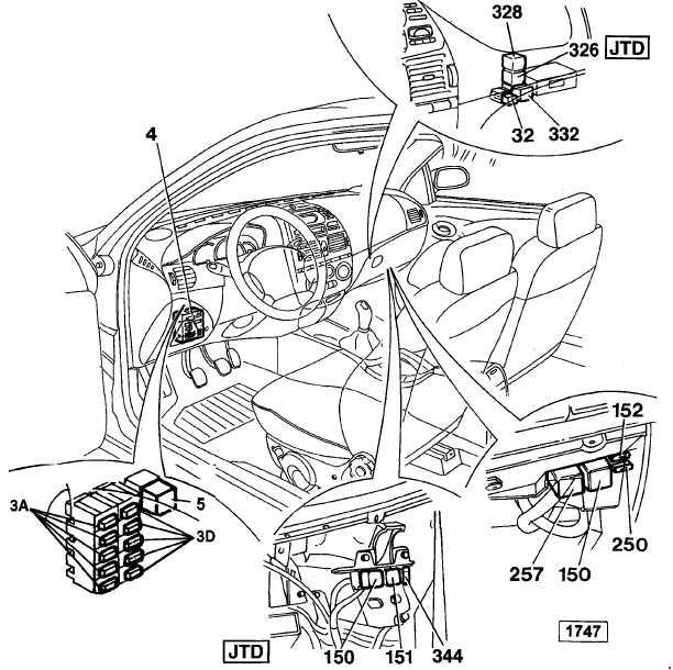
Fiat Marea and Marea Weekend Type 185 (1996-2002) have a main 15-fuse panel under the dashboard, an additional connector/fuse carrier labelled 3A/3D above it and engine-bay MAXI links and relay groups. The saloon, Weekend estate, petrol, 1.9 TD/JTD and 2.4 JTD variants use distinct equipment and fuse allocations. This article separates the original 1998, 1999 and 2000 wiring arrangements rather than treating all Mareas as electrically identical.
All 130 original table rows are preserved across ten complete tables, including alternative engine-fan currents, optional engine relays, unused slots and auxiliary component codes. The six existing model-specific drawings remain in the article and are placed beside their appropriate fuse tables. The official Fiat Marea workshop electrical volumes for the 1999 and 2000 ranges confirm the changes to the supplementary 3A/3D carrier and the 30 A 3D-F5 cigarette lighter feed.
Where are the Fiat Marea fuse boxes?
Main passenger compartment: switch off ignition and all electrical consumers. On left-hand-drive cars, find the rectangular fuse carrier below the driver’s dashboard, near the left side of the steering column. Release the retaining screws or clips of the lower trim and carefully pivot the fuse panel down towards you. Fiat workshop diagrams identify 15 numbered fuses and three relays E1-E3 on the reverse. Read the physical slot code and legend before removing a fuse.
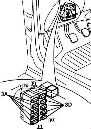
Supplementary 3A/3D unit: immediately above the main cabin junction unit, two separate six-fuse connector sections are installed. 3A serves the forward wiring and 3D the dashboard/facia wiring. Their identical F1-F6 numbers refer to different connector groups. To reach them, open or lower the fuse-carrier assembly without pulling on the wiring harnesses. The protected devices of 3A changed between the 1999 and 2000 service arrangements.
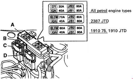
Engine compartment: locate the power distribution housing near the battery. Undo the retaining cover screw, remove the MAXI fuse cover and compare the A-E, EFI, GLOW, IGN and J/B positions with the exact engine. Other relays and fuses can be mounted on brackets around the engine bay and near the ECU. A 1.9 or 2.4 diesel has additional glow-plug and sometimes second-fan or auxiliary heating circuits. Isolate the battery as specified by Fiat before servicing any bolted 30-80 A link.
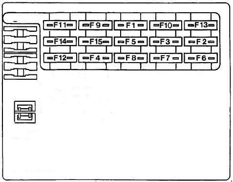
Main dashboard fuse box – 1999 version, 15 entries
The 1999 factory main panel is numbered F1-F15. Fuse 1 normally carries 10 A for brake lights, indicators and cluster, but Fiat specifies 15 A for a vehicle fitted with the relevant towing hook electrics. F11 (30 A) protects the heated rear window and mirrors, F12 (30 A) the air-conditioned blower, and F14 (20 A) the front/rear wiper and washer group. The cigarette lighter itself is not assigned to main F7 here; it is on supplementary 3D-F5 in the factory 1999 wiring.
| Pozycja | Amperaż [A] | Chroniony obwód / funkcja |
|---|---|---|
| 1 | 10 | Brake/stop lamps, high-level stop lamp, direction indicators and instrument cluster power; factory trailer-hook variants use 15 A instead of 10 A |
| 2 | 10 | Right front position lamp, left rear tail lamp, right licence plate light, radio and dashboard illumination, lighter backlight, switch illumination, automatic gearbox and heater/A/C panel lighting |
| 3 | 10 | Left front side lamp, right rear side/tail lamp, left number plate light and mirror-control backlighting |
| 4 | 10 | Right dipped-beam headlamp |
| 5 | 10 | Left dipped-beam headlamp, levelling system and headlamp washer controls |
| 6 | 10 | Right high-beam headlamp |
| 7 | 10 | Left high-beam headlamp and blue high-beam telltale |
| 8 | 20 | Central door locking and luggage compartment light, 1999 configuration |
| 9 | 10 | Hazard warning flashers |
| 10 | 10 | Front/rear cabin courtesy lamps, instrument supply, alarm/remote control receiver and telephone |
| 11 | 30 | Heated rear-window defogger and heated door mirrors |
| 12 | 30 | Heater blower on air-conditioned vehicles and A/C control module |
| 13 | 20 | Horn and horn relay power |
| 14 | 20 | Front and rear windscreen wipers, wash pumps and headlamp washer timer |
| 15 | 20 | A/C control and heater blower on basic heater-only variants |
Main dashboard fuse box – revised 2000 layout
The 2000 panel retains numbers F1-F15 but modifies some functions, particularly F8 through F14. Fuse F8 now also lists radio, F9 gains instrument-cluster power from January 2001, and F10’s cluster supply applies only up to December 2000. F13 (20 A) covers the horns as well as A/C control in this later layout. Using a 1999 list on a later car can therefore lead to checking the wrong circuit.
| Pozycja | Amperaż [A] | Chroniony obwód / funkcja |
|---|---|---|
| 1 | 10 | Brake/stop lamps, high-level brake light, turn indicators and instrument cluster; 15 A alternative when towbar fitted |
| 2 | 10 | Right front and left rear side lamps, right number plate lamp, radio/dash/automatic-transmission backlighting and HVAC controls |
| 3 | 10 | Left front and right rear position lamps, left number plate lamp and electric mirror switch backlight |
| 4 | 10 | Right dipped-beam headlamp |
| 5 | 10 | Left dipped-beam headlamp and levelling control, timed headlamp washer feed |
| 6 | 10 | Right high-beam headlamp |
| 7 | 10 | Left high-beam headlamp and telltale |
| 8 | 20 | Radio, central door locking and boot lamp; revised 2000 allocation |
| 9 | 10 | Hazard flashers and, from January 2001, the instrument cluster feed |
| 10 | 10 | Cabin lighting, cluster supply until December 2000, remote locking/alarm receiver, phone and diagnostic connector |
| 11 | 30 | Heated rear window and electric mirror demisting |
| 12 | 30 | Passenger cabin fan with factory air conditioning |
| 13 | 20 | Air-conditioning control electronics and horns |
| 14 | 20 | Front and rear wipe/wash motors and headlamp washer delay control |
| 15 | 20 | Climate control and cabin fan on heater-equipped non-A/C cars |
Relays E1-E3 on the back of the main fuse panel
E1 is the 30 A ignition/start-load shedding relay; E2 is the horn relay with 20 A contact capacity; E3 controls rear-window heating with 30 A contacts. These numbers indicate relay positions, and the amps describe contact ratings, not blade fuses to be fitted in those sockets.
| Pozycja | Amperaż [A] | Chroniony obwód / funkcja |
|---|---|---|
| E1 | 30 | E1 – ignition-start load reduction relay, contacts rated 30 A |
| E2 | 20 | E2 – horn relay, contacts rated 20 A |
| E3 | 30 | E3 – rear-window demister relay, contacts rated 30 A |
Supplementary dashboard fuses 3A and 3D – 1999 version
The two groups each have positions F1-F6, so the table uses combined short codes such as 3A-5 and 3D-5 to avoid collisions. In Fiat’s 1999 workshop manual, 3A-F5 (20 A) feeds headlamp washers, while 3D-F5 (30 A) supplies the cigarette lighter, electric front seats and sunroof. 3D-F3 and F4 protect rear/front power windows individually at 25 A.
| Pozycja | Amperaż [A] | Chroniony obwód / funkcja |
|---|---|---|
| 3A-F1 | 7.5 | 3A-F1 – electronic injection ECU memory and FIAT CODE immobiliser |
| 3A-F2 | 7.5 | 3A-F2 – air-conditioning compressor and control |
| 3A-F3 | 10 | 3A-F3 – ABS electronic supply |
| 3A-F4 | 7.5 | 3A-F4 – fuel injection electronics and FIAT CODE |
| 3A-F5 | 20 | 3A-F5 – headlamp washer motors |
| 3A-F6 | 7.5 | 3A-F6 – terminal 15/54 ignition-switched consumers |
| 3D-F1 | 7.5 | 3D-F1 – terminal INT ignition-switched consumers |
| 3D-F2 | 15 | 3D-F2 – front fog lamps |
| 3D-F3 | 25 | 3D-F3 – electric rear door windows |
| 3D-F4 | 25 | 3D-F4 – electric front door windows |
| 3D-F5 | 30 | 3D-F5 – electric sunroof, electric seats and cigarette lighter power |
| 3D-F6 | 10 | 3D-F6 – SRS airbag controller |
Supplementary dashboard fuses 3A and 3D – 2000 version
The 2000 Fiat wiring update reassigns 3A-F1 through F6: 3A-F2 (20 A) now feeds the headlamp washer system and 3A-F5 (7.5 A) the compressor and air-conditioning circuit. The 3D group remains 7.5/15/25/25/30/10 A with the same general functions. The physical location and number of sockets may look familiar, but the older 3A functions cannot be transferred into the later unit.
| Pozycja | Amperaż [A] | Chroniony obwód / funkcja |
|---|---|---|
| 3A-F1 | 7.5 | 3A-F1 – terminal 15/54 ignition-switched power, revised 2000 carrier |
| 3A-F2 | 20 | 3A-F2 – headlamp washing equipment, moved from 1999 3A-F5 |
| 3A-F3 | 7.5 | 3A-F3 – fuel injection, FIAT CODE and cooling fan on equipped versions |
| 3A-F4 | 10 | 3A-F4 – ABS electronic protection |
| 3A-F5 | 7.5 | 3A-F5 – air-conditioning compressor and control, moved from 1999 3A-F2 |
| 3A-F6 | 7.5 | 3A-F6 – engine injection ECU memory, FIAT CODE and cooling fan circuits, engine dependent |
| 3D-F1 | 7.5 | 3D-F1 – terminal INT ignition-switched consumers |
| 3D-F2 | 15 | 3D-F2 – front fog lights |
| 3D-F3 | 25 | 3D-F3 – electric rear windows |
| 3D-F4 | 25 | 3D-F4 – electric front windows |
| 3D-F5 | 30 | 3D-F5 – sunroof, electric seats and cigarette lighter feed |
| 3D-F6 | 10 | 3D-F6 – airbag controller |
Additional passenger compartment fuses and modules – identification codes
Fiat’s detailed wiring drawings also identify individual modules and relays by numbers such as 32, 150, 151, 152, 250, 257, 326 and 332. These are component reference numbers rather than ordinary fuse amp ratings. The source gives no universal current values for them; the second table column therefore contains “-“. The 3A/3D illustration above shows the auxiliary carrier area but not every remote relay bracket.
| Pozycja | Amperaż [A] | Chroniony obwód / funkcja |
|---|---|---|
| 3A/3D | – | 3A/3D – supplementary fuse and connector block beneath dashboard |
| 4 | – | 4 – main passenger-compartment junction unit with regular fuse carrier |
| 5 | – | 5 – dipped-beam headlamp relay supply |
| 32 | – | 32 – front fog lamp relay |
| 150 | – | 150 – petrol/diesel fuel injection electronic power relay, depending on engine |
| 151 | – | 151 – oxygen-sensor heater, petrol pump and fuel injectors control relay, engine dependent |
| 152 | – | 152 – supplementary fuel injection fuse |
| 250 | – | 250 – fuel pump fuse on relevant 1747 cc engines |
| 257 | – | 257 – fuel pump relay on relevant 1747 cc engines |
| 326 | – | 326 – supplementary heating control module |
| 328 | – | 328 – hazard warning flasher relay |
| 332 | – | 332 – ignition-switched supply relay |
| 344 | – | 344 – supplementary JTD injection fuse |
Main engine compartment MAXI fuses – 1999/2000 variants
Under the bonnet, EFI (30 A) protects petrol injection, while GLOW (60 A) for 1.9 TD/JTD or 70 A for 2.4 JTD feeds diesel preheating. IGN (40 A) supplies the ignition switch; both J/B1 and J/B2 are 80 A in this documented Fiat service arrangement. The radiator fan fuse identified as B may be 30, 40 or 50 A according to the engine and air-conditioning installation. C (60 A) protects ABS, D (40 A) an additional diesel cooling fan and E (30 A) JTD electronic injection.
| Pozycja | Amperaż [A] | Chroniony obwód / funkcja |
|---|---|---|
| EFI | 30 | EFI – petrol engine electronic injection main feed |
| GLOW | 60 | GLOW – diesel 1.9 TD75 and 1.9 JTD glow-plug preheat feed |
| GLOW | 70 | GLOW – diesel 2.4 JTD glow-plug preheat alternative |
| IGN | 40 | IGN – ignition switch and associated power distribution |
| J/B1 | 80 | J/B1 – main vehicle electrical distribution |
| J/B2 | 80 | J/B2 – second main vehicle power distribution |
| B | 30 | B – cooling fan supply for petrol cars without A/C |
| B | 40 | B – 40 A cooling fan variant on selected 1.2, 1.6, later 1.8 A/C, JTD and 1.9 TD75 |
| B | 50 | B – 50 A cooling fan variant on selected 1.8 and 2.0 petrol with A/C |
| C | 60 | C – ABS main high-current fuse |
| D | 40 | D – second radiator fan on specific diesel installations |
| E | 30 | E – supplementary electronic injection supply on JTD diesels |
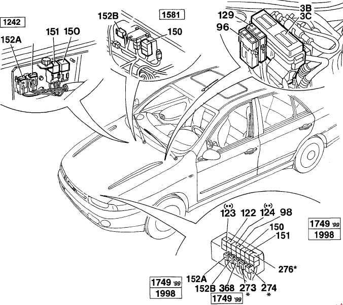
Petrol engine compartment auxiliary fuses and relays – 1999
This reference block includes the high-current 3B/3C carrier, separate ABS and fan fuses, headlamp washer timing, low/high cooling fan relays, compressor relay, petrol injection components and the automatic transmission protection fitted to certain versions. The 1999 engine component codes 122, 123, 124 and 129 do not denote ordinary numbered positions F1-F15 from the passenger compartment.
| Pozycja | Amperaż [A] | Chroniony obwód / funkcja |
|---|---|---|
| 3B-3C | – | 3B/3C – main engine compartment high-current fuse carrier, 1999 petrol |
| 96 | – | 96 – ABS main current fuse |
| 98 | – | 98 – headlamp washer timer/control unit |
| 122 | – | 122 – radiator fan low-speed relay |
| 123 | – | 123 – radiator fan high-speed timer or relay |
| 124 | – | 124 – A/C compressor clutch relay, if fitted |
| 129 | – | 129 – radiator cooling fan main fuse |
| 150 | – | 150 – engine fuel injection electrical relay |
| 151 | – | 151 – oxygen sensor, fuel pump and injection controller relay |
| 152 | – | 152 – engine injection fuse |
| 152A | – | 152A – supplementary engine injection fuse |
| 152B | – | 152B – additional engine injection protection |
| 273 | – | 273 – automatic gearbox fuse, when equipped |
| 274 | – | 274 – second automatic gearbox fuse, when equipped |
| 276 | – | 276 – starter permission relay on applicable automatic transmission |
| 368 | – | 368 – injection control circuit relay diode, 1999 petrol version |
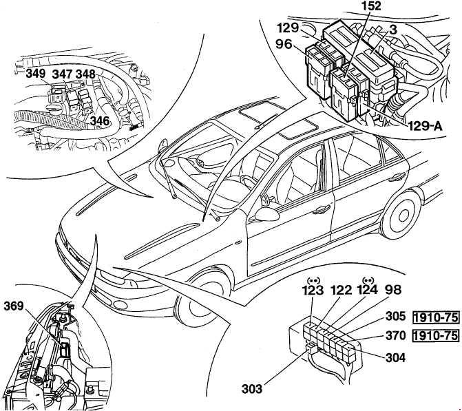
TD and JTD engine bay protection and relays
Diesel installations include the main 3B/3C power carrier, high-current ABS, one or two radiator cooling fans, glow-plug protection (303/304), diesel supplementary heater circuits 346-349, and engine-specific cooling or inertia-switch relays. The older 1.9 TD75 has its own 305 A/C cut-out and 370 inertia-related relay references; these are not universal for every 1.9 JTD or 2.4 JTD.
| Pozycja | Amperaż [A] | Chroniony obwód / funkcja |
|---|---|---|
| 3B-3C | – | 3B/3C – diesel main power fuse carrier |
| 96 | – | 96 – ABS main fuse |
| 98 | – | 98 – headlamp wash timed control |
| 122 | – | 122 – radiator cooling fan low-speed relay |
| 123 | – | 123 – engine fan high-speed control/relay |
| 124 | – | 124 – A/C compressor relay, if equipped |
| 129 | – | 129 – radiator cooling fan main fuse |
| 129A | – | 129A – second cooling fan high-current fuse on fitted diesels |
| 152 | – | 152 – diesel electronic injection fuse |
| 303 | – | 303 – diesel glow-plug preheater main fuse |
| 304 | – | 304 – diesel preheater control/protection relay |
| 305 | – | 305 – A/C compressor cut-out relay on early 1.9 TD75 versions |
| 346 | – | 346 – auxiliary diesel heater relay |
| 347 | – | 347 – second auxiliary heater relay |
| 348 | – | 348 – auxiliary heating controller |
| 349 | – | 349 – auxiliary heating protection fuse |
| 369 | – | 369 – radiator fan electrical controller |
| 370 | – | 370 – inertia-switch-associated relay on earlier 1.9 TD75 circuits |
Earlier 1996-1998 engine bay component reference list
The original earlier service chart uses component numbers such as 90, 94, 96, 123A, 237, 250, 308 and 310. The 1999 petrol/diesel illustrations above are not confirmed to show the physical layout of every 1998 engine; therefore no mismatched drawing has been repeated for this table. The functions below retain all 14 older source entries, without inventing amp ratings.
| Pozycja | Amperaż [A] | Chroniony obwód / funkcja |
|---|---|---|
| 3 | – | 3 – original 1998 high-current engine fuse block |
| 90 | – | 90 – windscreen or headlamp wash protection depending on equipment |
| 94 | – | 94 – ABS system fuse |
| 96 | – | 96 – ABS high-current power link |
| 98 | – | 98 – headlamp washer timing unit |
| 122 | – | 122 – low-speed engine radiator cooling fan relay |
| 123A | – | 123A – high-speed engine fan relay |
| 124 | – | 124 – air-conditioning compressor clutch relay on A/C versions |
| 129 | – | 129 – main radiator cooling fan fuse |
| 150 | – | 150 – fuel injection controller relay |
| 237 | – | 237 – FIAT CODE immobiliser protection fuse |
| 250 | – | 250 – fuel pump fuse |
| 308 | – | 308 – combined fuel injection and FIAT CODE protection fuse |
| 310 | – | 310 – headlamp washing and A/C related protection |
Fiat Marea and Weekend – practical electrical symptoms
Cigarette lighter has no power: on the documented Fiat 1999 and 2000 3A/3D layouts, check 3D-F5 (30 A). Some generic online fuse diagrams refer to main F7 (20 A) on a different simplified layout; do not interchange those numbering systems without comparing the installed fuse cover. Inspect the accessory socket and any plug-in device for a short.
Rear defogger does not work: check main cabin F11 (30 A), reverse-side relay E3 (30 A contact rating) and heater grid terminals. Heater blower stopped: main F12 (30 A) on an A/C car or main F15 (20 A) on a heater-only version, then the fan speed controller. Wipers and washer stopped: main F14 (20 A), motor, stalk and washer pump circuit.
Only one dipped headlamp fails: check main cabin F4 for the right lamp or F5 for the left (10 A each), and headlamp connectors. Front or rear electric windows stopped: inspect supplemental 3D-F4 or 3D-F3 (25 A each) and their switches and door wiring.
Petrol engine starts intermittently: inspect the appropriate EFI (30 A) main fuse and the engine-specific 150/151/152 relay and protection group. Diesel cold start fault: check the version-specific GLOW 60 or 70 A supply, preheating controller and, where fitted, fuel heater circuitry. Radiator fan stopped: check fuse B using the exact 30/40/50 A engine rating and the corresponding 122/123 relays; avoid increasing the fuse to match another engine.
For another Fiat from the same period, see Fiat Punto II Classic, whose fuse boxes have different physical numbers. The English Fiat fuse diagram index contains other models and years; fuse labels are not interchangeable between Marea, Punto and Tipo.