
The Ford Focus IV Mk4 C519/CGE (2019) is the European fourth-generation Focus, introduced in 2018. It has an engine compartment fusebox near the 12 V battery, a passenger compartment fusebox below the front passenger glovebox and, with a factory-fitted towbar, a separate fuse in the trailer control module in the luggage compartment. The EcoBoost petrol and EcoBlue diesel electrical installations have different protected circuits.
The following 87 complete manufacturer-listed entries in three tables include 61 engine fuse assignments, 25 passenger-compartment positions and one original trailer module fuse. There are no invented intermediary numbers between the engine fuse positions. In particular 4A and 4B are petrol/diesel fuel pump alternatives, while 6 and 65 can have different amp ratings by engine or manual edition.
Cigarette lighter and 12 V accessory sockets: engine fusebox 32, 33 and 34 (20 A each). The three circuits are independent on the illustrated 2019 European arrangement, and some equipment versions have fewer physical sockets installed.
Where are the Ford Focus Mk4 2019 fuse boxes?
Engine bay: stop the vehicle, switch off the ignition and electrical loads and open the bonnet. Locate the black protected fuse distribution unit next to the 12 V battery, at the side of the engine compartment. Release the lid retaining clips carefully. On some versions fuses are also on the underside of the carrier: release its two housing clips, raise and turn the carrier as described in Ford service instructions and unlatch the inner cover. Never pull on the wiring loom. Refit all covers fully to prevent moisture damage.
Front passenger footwell: this Mk4 model has its interior fuse panel under the glovebox on the passenger side, not beneath the steering wheel. Open the front passenger door, move the seat back and remove the lower glovebox trim cover without forcing the clips. Locate fuses 1-25, then refit the protective trim so that it cannot obstruct footwell ventilation or occupants’ feet.
Factory towbar: where fitted on five-door and estate variants, open the boot and look behind the right-hand luggage compartment side trim. The control module has its own 15 A protected ignition circuit. Vehicles without a factory towing module or with aftermarket towbar electrics may not have this fuse at the location shown.
Engine compartment fuses – all 61 listed positions
The manufacturer numbers the actual listed fuses discontinuously, ranging from 1 to 185 without every number in between corresponding to a real cavity. The full table keeps every documented engine, ABS/ESC, BCM, power steering, starter, lighting, ventilation, 12 V socket, windshield, infotainment, towbar and diesel emission-control circuit.
Engine-specific alternatives: 4A (20 A) protects the EcoBlue diesel fuel pump while 4B (20 A) is assigned to the EcoBoost petrol pump. 6 (15/20 A) supplies PCM electronics with rating depending on petrol or diesel. The earlier Polish reference records 65 as either petrol battery monitoring at 5 A or diesel transmission electronics at 20 A, although Ford’s current online chart specifies only the diesel 20 A use. Verify the fuse-cover label and actual handbook before replacement.
Fuse 164 documentation discrepancy: the earlier Polish technical source identifies a diesel AdBlue dosing controller, but Ford’s currently published specification chart identifies interior door controls – diesel. The translation records that conflict, rather than silently claiming the same assignment applies to every 2019 build.
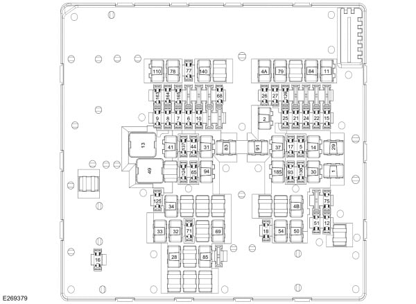
| Position | Amperage [A] | Protected circuit / function |
|---|---|---|
| 1 | 40 | Main power feed for the body control module BCM |
| 2 | 30 | Second main BCM power feed |
| 4A | 20 | Diesel EcoBlue electric fuel pump supply, alternate fuse 4A |
| 4B | 20 | Petrol EcoBoost electric fuel pump supply, alternate fuse 4B |
| 5 | 10 | Diagnostic DLC / OBD connector |
| 6 | 15 / 20 | PCM engine controller, 15 A petrol or 20 A diesel depending on powertrain |
| 7 | 10 | Powertrain control module PCM, circuit 7 |
| 8 | 15 | Powertrain control module PCM, circuit 8 |
| 9 | 20 | Powertrain control module PCM, circuit 9 |
| 10 | 10 | Petrol engine powertrain controller electronics |
| 11 | 30 | Starter motor supply and starting control |
| 12 | 10 | Air conditioning compressor clutch |
| 13 | 40 | Cabin heater and air-conditioning blower motor |
| 14 | 20 | Auxiliary heater controller if fitted |
| 15 | 20 | Vehicle horn |
| 16 | 20 | Rear window washer pump |
| 17 | 5 | Electric front-seat lumbar adjustment, where installed |
| 18 | 20 | Headlamp washer pump if fitted |
| 21 | 10 | Headlight beam levelling control |
| 22 | 5 | EPAS electric power-assisted steering low-current electronics |
| 24 | 10 | Additional powertrain control module feed |
| 25 | 10 | Front and rear cameras, blind-spot sensor and reverse gear detection, equipment dependent |
| 26 | 15 | Diesel automatic transmission controller |
| 27 | 10 | Electronic stability control ESC electronic control circuit |
| 28 | 40 | ESC/ABS hydraulic valve unit |
| 29 | 60 | ESC/ABS high-current hydraulic pump |
| 30 | 25 | Powered driver seat adjustment |
| 31 | 25 | Powered passenger seat adjustment |
| 32 | 20 | First auxiliary 12 V power outlet, if fitted |
| 33 | 20 | Second 12 V accessory outlet |
| 34 | 20 | Third 12 V accessory outlet |
| 37 | 20 | Electric sunroof or panoramic roof motor |
| 41 | 30 | Electric tailgate drive controller |
| 44 | 10 | Stoplight / brake pedal switch |
| 49 | 60 | Engine radiator cooling fan main supply |
| 50 | 30 | Heated rear window |
| 54 | 20 | Electronic limited-slip differential on specific petrol variants |
| 65 | 5 / 20 | Diesel transmission control module (20 A) or petrol battery monitoring circuit (5 A), depending on handbook edition and equipment |
| 68 | 20 | Electronic steering-column lock |
| 69 | 30 | Front windscreen wiper motor |
| 71 | 20 | Rear window wiper motor |
| 75 | 10 | Petrol engine mass airflow MAF and intake air temperature sensor |
| 77 | 10 | Heated windscreen washer jets and windscreen heating relay |
| 78 | 40 | Left heated windscreen element |
| 79 | 40 | Right heated windscreen element |
| 83 | 40 | First high-current supplementary cabin heater feed |
| 84 | 60 | Second high-current supplementary heater feed |
| 85 | 40 | Third high-current supplementary heater feed |
| 91 | 40 | Factory trailer tow electrical controller |
| 93 | 5 | Headlamp system power supply |
| 94 | 20 | Heated front seats |
| 110 | 30 | Diesel water-in-fuel sensor and fuel filter heater |
| 124 | 5 | Automatic rain sensor |
| 126 | 5 | Diesel AdBlue reductant dosing control module |
| 136 | 15 | First factory audio amplifier |
| 137 | 15 | Second factory audio amplifier |
| 140 | 60 | Diesel glow-plug controller |
| 163 | 15 | Diesel AdBlue pressure pipe heater |
| 164 | 10 | Diesel-only circuit: earlier Polish source identifies AdBlue dosing, while Ford’s current online chart identifies interior door controls; verify VIN and manual edition |
| 165 | 15 | Diesel AdBlue fluid tank heater |
| 185 | 20 | Electric windows and optional panoramic roof |
Passenger-compartment fusebox – all 25 positions
Behind the lower glovebox cover the 25 fuses supply airbags, central locking, electric windows and mirrors, comfort electronics, infotainment, climate control, telematics, factory alarm, electric roof and tailgate systems. Every position is retained, including 24 (20 A) and 25 (30 A), which Ford marks as spare rather than assigning protected consumers.
Key checks include 5 (20 A) for central locking, 7 and 14 (30 A each) for right and left front electric windows, 17 (15 A) for voice control and audio, and 23 (20 A) for the radio. The actual physical fuse population depends on factory options.
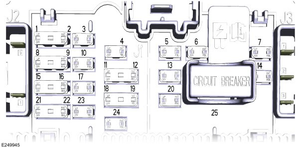
| Position | Amperage [A] | Protected circuit / function |
|---|---|---|
| 1 | 5 | Supplemental restraint system SRS airbag controller |
| 2 | 5 | Interior cabin temperature and humidity sensor |
| 3 | 10 | Active parking assist controller |
| 4 | 10 | Ignition switch and START/STOP push-button control |
| 5 | 20 | Central door locking |
| 6 | 10 | Electric moonroof or panoramic sunroof |
| 7 | 30 | Right mirror control and right front power window |
| 8 | 5 | Headlamp electronics control unit |
| 9 | 5 | Passenger airbag deactivation indicator, auto-dimming mirror and front parking camera |
| 10 | 10 | Head-up display HUD and wireless phone charger |
| 11 | 5 | Telematics communication modem |
| 12 | 5 | Central alarm and security electronics module |
| 13 | 15 | Child safety locks, fuel filler cover and central door locking |
| 14 | 30 | Left mirror control and left front power window |
| 15 | 15 | Steering wheel control electronics |
| 16 | 15 | Adaptive damping suspension controller, if fitted |
| 17 | 15 | Factory radio and voice recognition electronics |
| 18 | 7.5 | Electric tailgate and hands-free rear door actuation |
| 19 | 7.5 | Backup-battery theft alarm siren |
| 20 | 10 | Anti-theft alarm horn |
| 21 | 7.5 | Electronic cabin climate control and gear selector |
| 22 | 7.5 | Steering wheel module, instrument cluster and diagnostics |
| 23 | 20 | Factory radio/audio unit main feed |
| 24 | 20 | Spare 20 A fuse with no assigned consumer |
| 25 | 30 | Spare 30 A fuse with no assigned consumer |
Additional factory trailer module fuse
The original Ford towing kit uses a separate 15 A ignition-supply fuse at position 1 of its trailer control module on five-door and estate versions. The schematic below is a simplified identification of this single fuse, not a scale model of the actual module. Aftermarket trailer harnesses can have different relay and fuse locations.
| Position | Amperage [A] | Protected circuit / function |
|---|---|---|
| 1 | 15 | Ignition-switched supply to original trailer towing module, only on equipped five-door hatchbacks and estate cars |
EcoBoost petrol, EcoBlue diesel and production-year variations
Ford Focus IV powertrains and options affect the installation: petrol engines have their own fuel-pump and ignition controls, while diesels may add water-in-fuel detection and heating (110), glow plug power (140), AdBlue system power (126, 163 and 165) and diesel-specific transmission supplies. Manual/automatic gearboxes, adaptive dampers, glass roof, electric seats, heated front windscreen and audio amplifiers are optional in different model lines.
The Ford online owner manual can differ from the factory printed handbook for a particular build. If the physical box differs, select the diagram by VIN, build date, engine code, gearbox and destination market, rather than automatically adopting an adjacent model year. Do not copy the older Mk3 fuse allocation into a Mk4.
Practical electrical fault diagnosis
Front or rear 12 V socket fails: identify its location and check engine 32, 33 or 34 (20 A). Disconnect chargers and inspect the contacts for damage or shorted metal objects. Other sockets may still work because they are on separate circuits.
Front wipers do not work: inspect engine 69 (30 A), the wiper motor and linkage. The rear wiper uses engine 71 (20 A); a single rear-only fault can also come from wiring at the tailgate hinge.
Rear-window heater does not work: check engine 50 (30 A) and rear window heater tracks. With an electrically heated windscreen, left and right circuits are separately protected by 78 and 79 (40 A each).
Cabin ventilation blower is silent: engine 13 (40 A) supplies the heater fan. A fan that operates only at certain speeds may have a failed electronic controller instead of a blown fuse.
Door locks or front power windows fail: check cabin 5 (20 A) for central locking, or cabin 7/14 (30 A) for the respective front window and mirror controls. Door-hinge cable damage can cause one door to fail with other doors still working.
ESC/ABS warning: check engine 27 (10 A), 28 (40 A) and 29 (60 A), but read electronic fault codes and verify module power and wheel-speed sensors before replacing major components. For starter problems, inspect the 12 V battery and engine 11 (30 A) as well.
Repeated fuse failure: never install a fuse with a higher current rating. Inspect wiring, motor or control module for short circuits, particularly on power windows, fans and accessory sockets.
Related Ford fuse diagrams
See the earlier Ford Focus Mk3 Facelift (2015) and Ford Focus Mk2 Facelift (2007-2011) to identify clearly different electrical generations. The Ford Kuga Mk2 (from 2013) has related Ford technologies but uses a different fusebox arrangement.
Manufacturer references: Ford 2019 Focus (C519) owner manual, “Fuses – Fuse Specification Chart”, and the current Ford online specification chart for the engine, passenger compartment and factory trailer-tow module. The earlier reference’s model-specific 164 assignment is noted where it conflicts with the currently published source.
Featured vehicle photograph: Vauxford, “2019 Ford Focus Style 1.0 Front.jpg”, Wikimedia Commons, CC BY-SA 4.0, unmodified. Attribution and licence details remain in the media attachment.