
Ford Fusion Europe (CX70, 2002-2012) is a tall hatchback based on the Fiesta Mk6 platform. It is not the American Ford Fusion saloon, which uses a completely different electrical system. European cars have two distinct central fuse-box versions: the early F1-F56 arrangement and the later F30-F82 arrangement, generally introduced during the mid-2000s model update.
The six complete tables reproduce all 145 original fuse and relay entries, including unused positions, petrol and diesel alternatives, 8 high-current links and 4 engine relay positions. Four original illustrations are retained and an additional illustration specifically showing the late F30-F82 fuse panel has been added. The 2004 model year is transitional: identify the installed fuse holder, not just the first registration date.
Where are the European Ford Fusion fuse boxes?
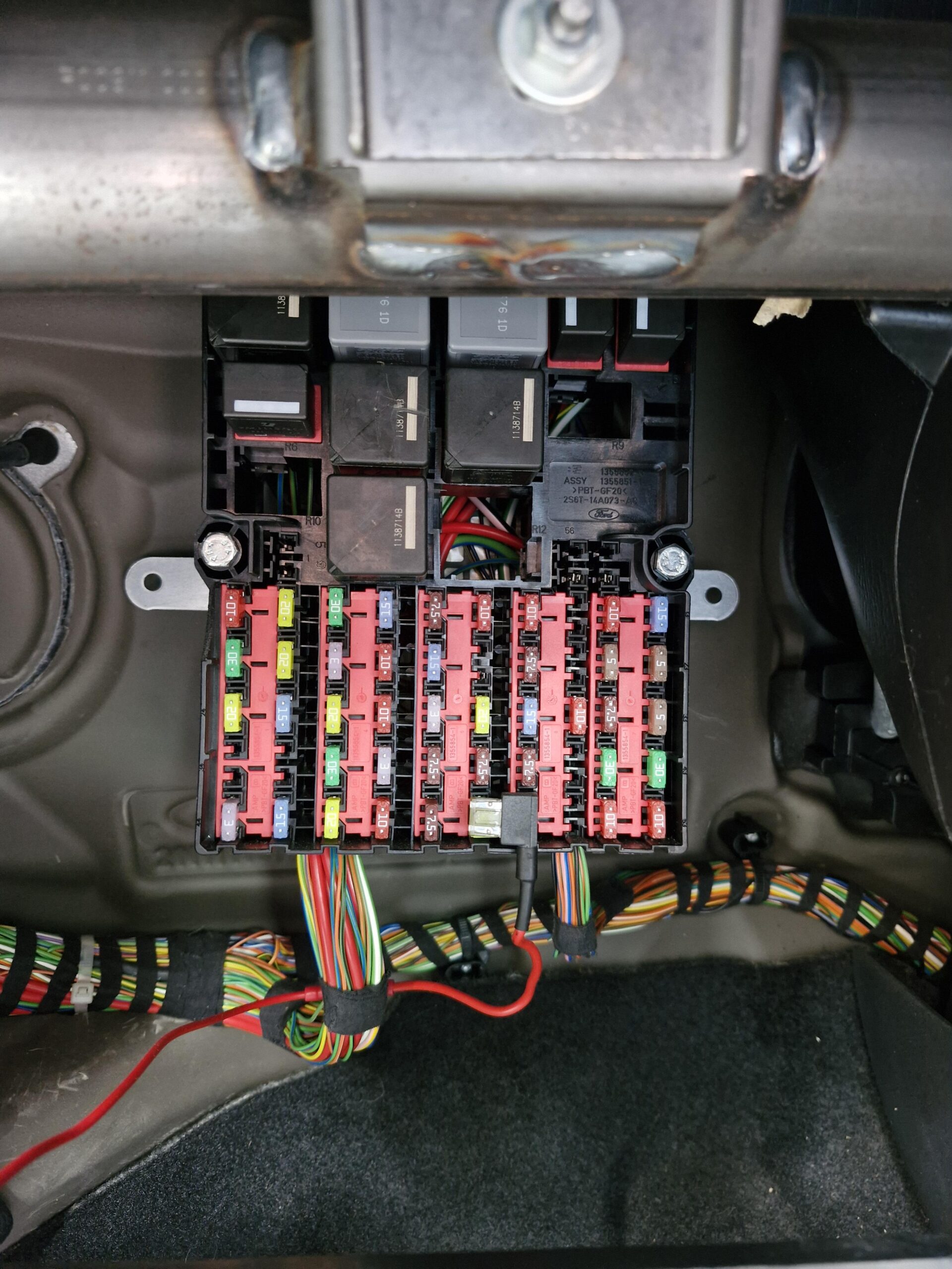
Passenger compartment: turn off the ignition and remove everything from the glovebox in front of the passenger. Squeeze the glovebox sides together to release their stops and fold the compartment down. The central junction box and its relay board sit immediately behind it. On left-hand-drive cars this is the passenger side; do not follow an American Fusion owner’s manual that locates a different fuse panel near the driver’s pedals.
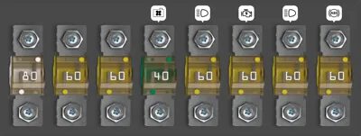
Engine compartment: the high-current fuse block is mounted against the battery tray and positive supply, with an additional relay box beside the battery. Service access may require lifting or removing the battery after correct electrical isolation. Release the clips, inspect the FA-FH fusible links and, after servicing, restore the protective cover and battery securing hardware. Never bridge a failed 40-80 A link with wire.
How to identify the right fuse diagram
Older cars have numbered fuse positions F1-F56 and a group of twelve R1-R12 relays. Revised cars have the main fuse series F30-F82 and relays R17-R28. They look and behave differently. Most importantly, the cigarette lighter is F29 (15 A) on the older panel, but F58 (15 A) on the later panel. The old F51 (15 A) is an auxiliary 12 V outlet, while later F51 controls the mirrors, so these identically numbered positions are not interchangeable.
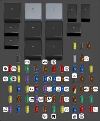
Early central fuse panel – full F1-F56 allocation
The early panel includes a separate main and accessory socket, radiator fan, GEM electronics, airbags, ABS/ESP, heated screens, power windows, lamps and trailer options. F42 and F43 (30 A each) protect the left and right sections of the heated front screen. ABS-related circuits include F5 (20 A), F6 (30 A) and F37 (3 A). F1, F21 and F55 remain unused in the original equipment chart.
| Pozycja | Amperaż [A] | Chroniony obwód / funkcja |
|---|---|---|
| F1 | – | Unused position |
| F2 | 7.5 | Exterior lighting, configuration dependent |
| F3 | 7.5 | Exterior lighting |
| F4 | 10 | Engine control and air conditioning |
| F5 | 20 | ABS and ESP electronic control |
| F6 | 30 | ABS and ESP hydraulic supply |
| F7 | 7.5 | Automatic or automated gearbox controller, if fitted |
| F8 | 7.5 | Electrically adjustable mirrors |
| F9 | 10 | Left dipped headlamp / exterior lights, by version |
| F10 | 10 | Right dipped headlamp / exterior lights, by version |
| F11 | 15 | Daytime running lights |
| F12 | 15 | Engine ECU, cooling, charging, auxiliary heating, A/C and alarm, engine dependent |
| F13 | 20 | Engine management and charging, supplementary heater and petrol oxygen sensor, by configuration |
| F14 | 30 | Starter motor relay and ignition |
| F15 | 20 | Fuel pump / engine control, engine-specific |
| F16 | 3 | PCM keep-alive memory and charging |
| F17 | 15 | Lighting switch, exterior lamps, factory DRL |
| F18 | 15 | Audio, diagnostics connector, navigation and multimedia |
| F19 | 15 | Daytime running light circuit |
| F20 | 7.5 | Instruments, GEM, courtesy lights and battery-saver control |
| F21 | – | Unused position |
| F22 | 7.5 | Left side and tail lights, optional trailer electronics |
| F23 | 7.5 | Right side and tail lights, optional trailer electronics |
| F24 | 20 | GEM controller, central door locking and alarm |
| F25 | 15 | Hazard flashers, indicators, GEM and alarm |
| F26 | 20 | GEM, electric windows and rear screen heating, by equipment |
| F27 | 10 | GEM, horn, interior lights and instrument cluster |
| F28 | 3 | Alternator and charging circuit |
| F29 | 15 | Cigarette lighter / front 12 V power socket |
| F30 | 15 | Ignition and automatic transmission, according to equipment |
| F31 | 20 | Lighting / trailer module |
| F32 | 7.5 | Electric mirror controls and demister system |
| F33 | 7.5 | Audio, instruments, climate control, hazard switch, GEM and gearbox circuits |
| F34 | 20 | Electric sunroof |
| F35 | 7.5 | Heated front seats |
| F36 | 30 | Power windows |
| F37 | 3 | ABS and ESP electronics |
| F38 | 7.5 | GEM, A/C, instruments, alarm, locking, wipers, optional equipment |
| F39 | 7.5 | SRS airbags and belt pretensioners |
| F40 | 10 | Lighting switch, turn indicators, exterior lights and DRL |
| F41 | 7.5 | Durashift EST gearbox |
| F42 | 30 | Heated windscreen left section |
| F43 | 30 | Heated windscreen right section |
| F44 | 3 | Radio, instrument cluster, navigation / multimedia |
| F45 | 15 | Stop/brake lamps and pedal switch |
| F46 | 20 | Front windscreen wipers, washer and GEM |
| F47 | 10 | Rear wiper, or high-speed front wipe in some versions |
| F48 | 7.5 | Reverse lights, Durashift gearbox and parking assistance |
| F49 | 30 | Heater / air conditioner cabin blower |
| F50 | 20 | Front fog lights and main lighting switch |
| F51 | 15 | Auxiliary 12 V socket, battery saver circuit |
| F52 | 10 | Left high-beam headlamp |
| F53 | 10 | Right high-beam headlamp |
| F54 | 7.5 | Trailer towing module |
| F55 | – | Unused position |
| F56 | 20 | Trailer towing module |
Early relay carrier – R1-R12
Among the relays are separate low- and high-beam lights, engine cooling, ignition, fuel pump, PCM and battery saver control. The source does not establish one fixed function for R10; its assignment is deliberately not invented. These R1-R12 positions belong to the passenger fuse board and are not the same as the under-bonnet R1-R4 relay sockets.
| Pozycja | Amperaż [A] | Chroniony obwód / funkcja |
|---|---|---|
| R1 | – | Main-beam headlamp relay |
| R2 | – | Dipped-beam headlamp relay |
| R3 | – | Daytime-running-lamp relay |
| R4 | – | Ignition relay |
| R5 | – | Radiator cooling fan relay |
| R6 | – | Alarm and warning relay |
| R7 | – | Heated front windscreen relay |
| R8 | – | Immobiliser relay |
| R9 | – | PCM engine management relay |
| R10 | – | Equipment-specific position; assignment not confirmed |
| R11 | – | Fuel pump relay |
| R12 | – | Battery saver relay |
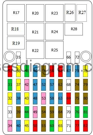
Later central fuse panel – F30-F82
The revised panel has 53 fuse entries and a different physical diagram. Its cigarette lighter is F58 (15 A), the petrol fuel pump F37 (20 A), ABS valves F36 (20 A), ABS pump F41 (30 A) and ABS electronics F49 (3 A). F43 (20 A) protects the heated rear glass, F45 (20 A) the front wipers and F60 (30 A) the cabin ventilation blower. Positions without confirmed functions are retained as such, rather than assigned loads from another generation.
| Pozycja | Amperaż [A] | Chroniony obwód / funkcja |
|---|---|---|
| F30 | 10 | Air conditioning controls |
| F31 | 30 | Starter relay |
| F32 | 20 | Anti-theft alarm siren |
| F33 | – | Unused slot |
| F34 | 3 | Audio and instrument cluster |
| F35 | – | Unused slot |
| F36 | 20 | ABS hydraulic valves |
| F37 | 20 | Fuel pump |
| F38 | 15 | Hazard warning lights |
| F39 | 7.5 | Heated seats |
| F40 | 15 | Stop/brake lamps |
| F41 | 30 | ABS hydraulic pump |
| F42 | 3 | PCM engine management supply |
| F43 | 20 | Heated rear-window demister |
| F44 | 30 | Front electric windows |
| F45 | 20 | Front windscreen wipers |
| F46 | 15 | Automatic/Durashift transmission controller |
| F47 | 15 | Lighting switch |
| F48 | 15 | Horn and battery saver |
| F49 | 3 | ABS electronic controller |
| F50 | 10 | Rear windscreen wiper |
| F51 | 7.5 | Electric exterior mirrors |
| F52 | 15 | Onboard electronics, radio and DVD equipment |
| F53 | 3 | Alternator charging signal |
| F54 | 7.5 | Generic Electronic Module (GEM) |
| F55 | 7.5 | Reversing lights |
| F56 | 10 | Left dipped-beam headlamp |
| F57 | 15 | Daytime running lamp relay supply |
| F58 | 15 | Front cigarette lighter / 12 V socket |
| F59 | 7.5 | Airbag controller |
| F60 | 30 | Heater / ventilation blower motor |
| F61 | 10 | Right dipped-beam headlamp |
| F62 | 7.5 | Instrument cluster |
| F63 | 15 | Ignition switch |
| F64 | 7.5 | Automatic/Durashift transmission electronics |
| F65 | 20 | Front fog lamps |
| F66 | – | Trailer towing module; rating depends on installed equipment |
| F67 | 15 | Daytime running lamps |
| F68 | – | Unused position |
| F69 | 10 | Instrument dimmer, automatic light controls |
| F70 | – | Unused position |
| F71 | – | Function not confirmed by available source |
| F72 | – | Trailer control module, if equipped |
| F73 | 15 | Powertrain Control Module (PCM) |
| F74 | 7.5 | Left parking and position lamps |
| F75 | 7.5 | Heated exterior mirrors |
| F76 | 30 | Heating or front left power window, equipment-specific |
| F77 | 10 | Left high-beam headlamp |
| F78 | 20 | Oxygen sensor heating and PCM |
| F79 | 7.5 | Right parking / position lamps |
| F80 | 7.5 | Licence plate lamps |
| F81 | 30 | Heating or front right power window, equipment-specific |
| F82 | 10 | Right high-beam headlamp |
Later passenger relay carrier – R17-R28
The newer panel has a fuel pump relay at R18, starter at R21, PCM at R22, ignition at R23, fan at R24, and dipped/high-beam relays at R26/R27. R25 is unoccupied in the source and the function of R19 remains unconfirmed. The matching late-panel diagram directly precedes the relay list below.
| Pozycja | Amperaż [A] | Chroniony obwód / funkcja |
|---|---|---|
| R17 | – | Automatic headlamp controller |
| R18 | – | Fuel pump / auxiliary fuel pump relay, by version |
| R19 | – | Function not confirmed |
| R20 | – | Heating and heated front screen relay |
| R21 | – | Starter relay |
| R22 | – | PCM engine-management relay |
| R23 | – | Ignition circuit |
| R24 | – | Cooling fan |
| R25 | – | Unused position |
| R26 | – | Dipped-beam relay |
| R27 | – | Main-beam relay |
| R28 | – | Daytime-running-light relay |
Battery-mounted high-current fuse links FA-FH
The eight under-bonnet links supply the electric PTC heater, diesel glow plugs, fan and air conditioning, main ignition, GEM and exterior lighting, and ABS/ESP with the heated front screen. The same source also names these physical links F1-F8; the table retains both identifiers to avoid confusing a battery-main F1 with a passenger fuse F1. FA, FB and FC are fitted according to engine, gearbox and optional heater equipment.
| Pozycja | Amperaż [A] | Chroniony obwód / funkcja |
|---|---|---|
| FA | 80 | PTC auxiliary/coolant heater or coolant heater relay 2 (also F1 in the alternate 1-8 numbering) |
| FB | 60 | PTC auxiliary heater and automatic transmission TCU or coolant heater relay 1 (also F2 in the alternate 1-8 numbering) |
| FC | 60 | PTC cabin heater or diesel glow plug preheating (also F3 in the alternate 1-8 numbering) |
| FD | 40 | Engine cooling fan and air conditioning (also F4 in the alternate 1-8 numbering) |
| FE | 60 | Exterior lighting and main GEM power (also F5 in the alternate 1-8 numbering) |
| FF | 60 | Ignition main power distribution (also F6 in the alternate 1-8 numbering) |
| FG | 60 | Engine controls and lighting main power (also F7 in the alternate 1-8 numbering) |
| FH | 60 | Heated front screen, ABS and ESP high-current circuits (also F8 in the alternate 1-8 numbering) |
Engine compartment relay box – R1-R4
The four positions have two documented engine/equipment arrangements. One version uses R1 for the A/C compressor clutch, R2 for high-speed radiator cooling and R3/R4 for auxiliary PTC heating. Another uses R1/R2 for coolant heating, R3 for the cooling fan and R4 for A/C cut-out at wide-open throttle. All alternatives are preserved within the corresponding rows, not combined into a misleading universal fitment.
| Pozycja | Amperaż [A] | Chroniony obwód / funkcja |
|---|---|---|
| R1 | – | Variant A: air conditioning compressor clutch. Variant B: coolant heater relay 2 |
| R2 | – | Variant A: high-speed cooling fan. Variant B: coolant heater relay 1 |
| R3 | – | Variant A: auxiliary PTC heater. Variant B: high-speed radiator cooling fan |
| R4 | – | Variant A: auxiliary PTC heater. Variant B: A/C cut-out at wide-open throttle |
Practical Ford Fusion electrical fault checks
Front 12 V socket dead: check early F29 (15 A) or later F58 (15 A). On early cars a separate auxiliary socket uses F51 (15 A). Inspect the socket for loose metal or a charger short if the fuse fails repeatedly.
Heated front screen works only on one side: on an early car check F42 and F43 (both 30 A), then wiring to the corresponding half of the glass. The high-current FH (60 A) link may supply part of the system on equipped versions. The late panel has different physical numbering and must not be diagnosed solely from the early F42/F43 entries.
Engine cranks but fails to start: early petrol cars can use F15 (20 A) and R11 for the fuel pump, while later cars use F37 (20 A) and relay R18. Fuel delivery and the immobiliser must be checked if power is present.
Wipers stopped: early F46 (20 A) or later F45 (20 A) protect the front wiper system. Cabin blower dead: early F49 (30 A), later F60 (30 A), then check motor, wiring and speed regulator. ABS lamp on: compare early F5/F6/F37 or later F36/F41/F49 and retrieve diagnostic fault codes rather than swapping entire controllers.
For different Ford-era electrical layouts, see the Ford Ka Mk1 and Ford Fiesta Mk5. They do not share the European Fusion’s fuse slot numbering.