
Ford Ka Mk1 (1997-2008) was the original European Ford Ka, including later special editions. Its main fuse and relay panel is beneath the dashboard next to the steering column. The European owner’s handbook shows 22 numbered fuses in two rows, three separately described but unnumbered circuits and, on equipped vehicles, an extended relay carrier. Later cars can have more physical fuse positions than the simple 22-slot handbook drawing.
This guide retains all 54 entries in four tables from the Polish source: 22 basic fuses, three unnumbered supplementary circuits, 14 quick-reference circuit lookups and 15 relay descriptions. The quick-reference entries are not extra fuses. Ratings and occupancy must be checked against the installed fuse label, because Ka production-year, engine, ABS, air conditioning, alarm and remote-locking configurations differ.
Where is the Ford Ka Mk1 fuse box?
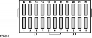
Park the vehicle safely, switch off the ignition and electrical accessories, and open the driver’s door. On a left-hand-drive European Ford Ka, the interior fuse panel is beneath the lower dashboard to the left of the steering column. Release and lower the plastic access cover carefully. On right-hand-drive models, the access panel is on the opposite side of the steering column. The position numbers are embossed near the two rows of fuses; the lower row covers 1-11 and the upper row 12-22 in the handbook diagram. Refitted panels should not press against wiring.
The larger relay bank and optional supplementary fuses are within or around the central carrier, depending on model year. A photographed panel may contain additional positions not shown in the simplified handbook drawing. Use the original card to identify the physical socket, especially when examining a fuse without a factory number.
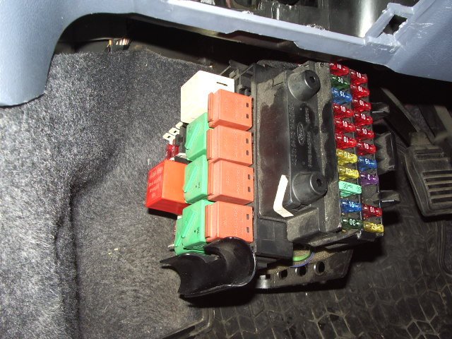
Complete European main fuse panel – positions 1-22
The cigarette lighter is F5 (15 A). F2 (10 A) serves interior lights, clock, radio and the diagnostic connector, F3 (30 A) the ABS controller, F12 (30 A) the cabin blower, and F19 (25 A) the fuel pump and ignition coil on the documented configuration. Both dipped and high beams are individually fused. The original European diagram is directly below; its printed ratings must be compared with the actual fuse card on cars fitted with later equipment.
| Pozycja | Amperaż [A] | Chroniony obwód / funkcja |
|---|---|---|
| F1 | 20 | Heated rear window, central locking and heated exterior mirrors |
| F2 | 10 | Interior lights, clock, radio and diagnostic connector |
| F3 | 30 | ABS control module |
| F4 | 3 | Engine control unit and main engine relay |
| F5 | 15 | Cigarette lighter / front 12 V socket |
| F6 | 10 | Left parking/position lights, dash lighting and lights-on warning buzzer |
| F7 | 10 | Right side/position lights and rear lights |
| F8 | 10 | Left dipped-beam headlamp |
| F9 | 10 | Right dipped-beam headlamp |
| F10 | 10 | Left high-beam headlamp and blue high-beam indicator |
| F11 | 10 | Right high-beam headlamp |
| F12 | 30 | Heater blower motor and recirculation motor |
| F13 | 15 | Light switch and stop/brake lights |
| F14 | 30 | Electric door windows |
| F15 | 20 | Main headlamp switch power circuit |
| F16 | 20 | Front windscreen wiper motor and washer pump |
| F17 | 15 | Air conditioning, ignition relay, instrument cluster, central locking and courtesy entry light |
| F18 | 10 | Supplemental Restraint System (SRS) airbag controller |
| F19 | 25 | Fuel pump and ignition coil/transformer |
| F20 | 15 | Electronic engine management |
| F21 | 10 | Rear fog lamp |
| F22 | 10 | Direction indicators |
Three auxiliary fuses without a factory position number
The original owner’s handbook lists extra 7.5 A, 15 A and 20 A circuits after main fuse positions 17, 20 and 21, but does not assign physical slot numbers. These are reproduced in their original sequence as U1-U3 reference identifiers created only for this table; U1, U2 and U3 are not stamped Ford fuse positions. The drawing above is the main 1-22 panel and does not show confirmed coordinates for these supplementary fuses.
| Pozycja | Amperaż [A] | Chroniony obwód / funkcja |
|---|---|---|
| U1 | 7.5 | Unnumbered extra entry after fuse 17: ignition relay, instrument cluster, fuel pump relay and engine ECU (factory manual did not provide a fuse number) |
| U2 | 15 | Unnumbered extra entry after fuse 20: engine electronics, ABS module and cooling fan relay (factory manual did not provide a fuse number) |
| U3 | 20 | Unnumbered extra entry after fuse 21: rear wiper motor, reverse lamp, air conditioning and heater water valve (factory manual did not provide a fuse number) |
Frequently checked circuits – reference index
The following 14 lines reproduce the original quick-reference lookup, pointing back to numbered fuses in the first table. They are not a separate fuse box or 14 additional physical positions. Useful examples include F5 for the 12 V socket, F16 for the windscreen wipers, F14 for electric windows, and F18 for SRS.
| Pozycja | Amperaż [A] | Chroniony obwód / funkcja |
|---|---|---|
| F5 | 15 | Cigarette lighter / front 12 V socket – summary reference to the first table, not an additional fuse |
| F3 | 30 | ABS controller – summary reference to the first table, not an additional fuse |
| F2 | 10 | Radio and audio – summary reference to the first table, not an additional fuse |
| F12 | 30 | Heater and ventilation blower – summary reference to the first table, not an additional fuse |
| F14 | 30 | Electric front windows – summary reference to the first table, not an additional fuse |
| F16 | 20 | Front windscreen wiper and washer – summary reference to the first table, not an additional fuse |
| F18 | 10 | Airbag system – summary reference to the first table, not an additional fuse |
| F19 | 25 | Fuel pump – summary reference to the first table, not an additional fuse |
| F21 | 10 | Rear fog lamp – summary reference to the first table, not an additional fuse |
| F22 | 10 | Turn indicators – summary reference to the first table, not an additional fuse |
| F8 | 10 | Left dipped headlamp – summary reference to the first table, not an additional fuse |
| F9 | 10 | Right dipped headlamp – summary reference to the first table, not an additional fuse |
| F10 | 10 | Left high-beam headlamp – summary reference to the first table, not an additional fuse |
| F11 | 10 | Right high-beam headlamp – summary reference to the first table, not an additional fuse |
Relay carrier – R1-R15 on the documented extended panel
Installed relays differ by manufacturing date, air conditioning, remote central locking and alarm equipment. The 15 positions in this reference may control the cooling fan, wipers, courtesy lights, ignition, heated rear glass, starter, headlamps, engine management and fuel pump. An empty relay socket can be correct. The simple 22-fuse drawing does not verify the physical layout of all 15 relay positions; inspect the relay-carrier identification before swapping components.
| Pozycja | Amperaż [A] | Chroniony obwód / funkcja |
|---|---|---|
| R1 | – | Cooling fan on cars without air conditioning |
| R2 | – | Front windscreen intermittent wiper relay |
| R3 | – | Interior courtesy lighting on cars with remote central locking |
| R4 | – | Front fog lamp relay |
| R5 | – | Main ignition relay |
| R6 | – | Heated rear-window relay |
| R7 | – | Starter inhibitor / control relay |
| R8 | – | Headlamp-on warning buzzer |
| R9 | – | Dipped-beam headlamp relay |
| R10 | – | High-beam headlamp relay |
| R11 | – | Engine-control relay |
| R12 | – | Fuel pump relay |
| R13 | – | Air-conditioning relay |
| R14 | – | Alarm turn indicators – left side, remote locking equipped |
| R15 | – | Alarm turn indicators – right side, remote locking equipped |
Ford Ka Mk1: year, market and optional circuit differences
The first Ka remained on sale for more than a decade, with changes to the fuse carrier. Other service diagrams list extra slots 23-36 and can show different ratings for F16, F17 and F19, as well as extra circuits for alarm, sunroof, alternator and radiator cooling. Do not transfer these later positions onto an older 1-22 carrier. The original fuse cover is the deciding reference, even when two vehicles have the same registration year.
The Ford Fiesta Mk4 (1996-1999) shares some Ford-era equipment, but uses its own fuse numbering. The Fiesta Mk5 (1999-2002) also has different main and engine compartment fuse arrangements.
Model-specific electrical checks
12 V outlet not working: inspect main F5 (15 A), then the cigarette lighter socket for metal debris or a damaged charger. Radio, clock and interior lights fail together: check F2 (10 A), and measure supply and earth at the radio or multifunction connector.
Front wipers inoperative: F16 (20 A) protects the wiper motor and washer pump in the documented European panel. Rear wiper stopped: inspect the supplementary 20 A circuit whose position is unnumbered in the source, plus the tailgate wiring and motor. Do not identify it using an unverified F-number.
Cabin blower completely dead: F12 (30 A) supplies the heating blower and recirculation motor. Power windows not moving: F14 (30 A) is the main supply, followed by door switches and wiring. Engine cranks but does not start: F19 (25 A) and the fuel pump relay may be relevant on the documented petrol model; the immobiliser and coil supply require separate testing.
ABS warning: check F3 (30 A) and any additional supply fitted to the ABS system, then retrieve fault codes. Use the installed fuse card rather than a fuse label from a different Ka production year.