Jeep Cherokee XJ vehicles from 1984 to 1996 used several different fuse and relay arrangements. The three retained diagrams and the main cabin and engine-bay tables in this guide describe the 1993-1996 installation. An additional complete cabin fuse table covers 1989-1991. Do not apply the 1993-1996 numbering to a 1984-1992 vehicle without a matching handbook. The earliest 1984-1988 wiring is not illustrated here because a verified complete diagram for those years has not been established.
Where are the Cherokee XJ fuse boxes?
Driver’s dashboard: On a left-hand-drive Cherokee, switch off the ignition and open the driver’s door. Look beneath the lower trim to the left of the steering column, open the panel access cover and compare each numbered position with its printed legend. Some locations contain resetting circuit breakers rather than ordinary blade fuses.
Separate cabin relay panel: On the 1993-1996 layout, a relay carrier with ten positions sits to the right of the steering column, behind the trim. The horn relay moved between positions on certain 1995 vehicles.
Engine compartment: Lift the bonnet and find the Power Distribution Center (PDC) under a plastic lid beside the battery. Release the cover catches, identify each numbered fuse and use the vehicle-specific chart. High-current ABS and alternator protection requires an appropriate diagnosis and replacement procedure.
Passenger compartment fuse box – 1993-1996 positions 1-20
The passenger panel protects wipers, 12 V lighter, heating, windows, lighting and the body electrical systems. Some positions are occupied by thermal circuit breakers, which must not be replaced with ordinary blade fuses.
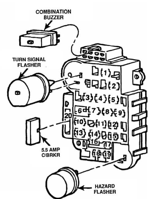
| Pozycja | Amperaż [A] | Chroniony obwód / funkcja |
|---|---|---|
| 1 | 25 | Rear window wiper and washer |
| 2 | 15 | Radio and cigarette lighter; also the overhead lamp on 1993 vehicles |
| 3 | – | Unused in the 1993-1996 arrangement; 1992 versions use 10 A for the alarm circuit |
| 4 | 15 | Headlamp flash-to-pass circuit |
| 5 | 25 | Heater / ventilation blower motor |
| 6 | 30 | Electric window circuit breaker, not a conventional blade fuse |
| 7 | 2 | ABS system |
| 8 | 20 | Turn signal flasher |
| 9 | 10 | Radio and clock memory, cabin, glovebox and luggage lamps, and warning indicators |
| 10 | – | Unoccupied position |
| 11 | 25 | Headlamp delay module and horn |
| 12 | – | Unoccupied position |
| 13 | 20 | Central door locking |
| 14 | – | Unoccupied position |
| 15 | 15 | Instrument, clock and radio illumination/memory and position lamp switch supply |
| 16 | 30 | Power seat and trailer circuit breaker, not an ordinary fuse |
| 17 | 7.5 | Instrument cluster and gauges, headlamp delay, chime and overhead console |
| 18 | 25 | Heated rear window |
| 19 | 5 | Instrument and radio display illumination |
| 20 | 5.5 | Front wiper and washer circuit breaker, not an ordinary fuse |
Cabin relay panel – 1993-1996
The 1993-1994 and 1995-1996 layouts are not identical. Position 2 changes from a horn relay to a combined indicator and hazard flasher; horn relay position 5 becomes populated on later variants.
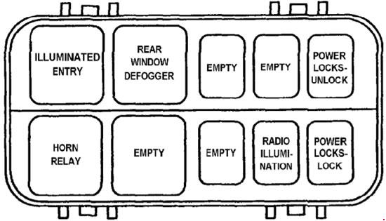
| Pozycja | Amperaż [A] | Chroniony obwód / funkcja |
|---|---|---|
| 1 | – | 1993-1994: courtesy lamp relay; unoccupied in 1995-1996 |
| 2 | – | 1993-1994: horn relay; 1995-1996: combined turn signal and hazard flasher |
| 3 | – | Heated rear window relay |
| 4 | – | Unoccupied position |
| 5 | – | 1993-1994: unused; 1995-1996: horn relay |
| 6 | – | Unoccupied position |
| 7 | – | Unoccupied position |
| 8 | – | Radio illumination relay |
| 9 | – | Central door unlocking relay |
| 10 | – | Central door locking relay |
Under-bonnet Power Distribution Center – 1993-1996
Positions 1-16 include alternator, engine control, ABS, headlamps and auxiliary cooling fan power feeds. Ratings can differ substantially on a 1991 or 1992 vehicle even when the location number appears the same.

| Pozycja | Amperaż [A] | Chroniony obwód / funkcja |
|---|---|---|
| 1 | 60 | Alternator output, first supply circuit |
| 2 | 30 | Engine management: fuel pump, injectors, ignition coil, oxygen sensors, alternator field and automatic transmission control |
| 3 | 40 | Main power supply for the cabin fuse board |
| 4 | 20 | Hazard warning lights |
| 5 | 40 | Headlamp switch power supply |
| 6 | 50 | Ignition and main engine-management feeds, fuel pump and automatic shutdown (ASD) relay in 1993-1996; 1992 vehicles used a 60 A rating here |
| 7 | 40 | Heated rear window and starter solenoid |
| 8 | 40 | ABS pump motor |
| 9 | 60 | Alternator output, second supply circuit |
| 10 | 30 | Additional ABS supply |
| 11 | 15 | Ignition, reversing lamps, air-conditioning relay, gearbox selector, cruise control and auxiliary cooling fan |
| 12 | 10 | Automatic transmission |
| 13 | 15 | Auxiliary and fog lamps, plus under-bonnet lighting |
| 14 | 20 | Engine control module |
| 15 | 20 | Auxiliary radiator cooling fan |
| 16 | 10 | IOD permanent feed for radio/clock memory, cabin lamps and other standby consumers |
Relays A-G in the same engine-bay box
The relays for the fuel pump, automatic shutdown supply, air conditioning, ABS and the auxiliary cooling fan are located in the under-bonnet PDC on these variants.
| Pozycja | Amperaż [A] | Chroniony obwód / funkcja |
|---|---|---|
| A | – | Auxiliary radiator cooling fan relay |
| B | – | Fuel pump relay |
| C | – | ABS pump relay |
| D | – | Air-conditioning compressor relay |
| E | – | Automatic shutdown (ASD) engine supply relay |
| F | – | Starter relay |
| G | – | ABS control relay |
Separate cabin arrangement – 1989-1991
The older Cherokee XJ passenger fuse board has 19 listed positions and different circuits. The following assignments are taken from the 1989-1991 Chrysler electrical documentation. The diagrams displayed above illustrate the 1993-1996 fuse boxes, not this earlier panel; use the original 1989-1991 vehicle documentation for location matching.
| Pozycja | Amperaż [A] | Chroniony obwód / funkcja |
|---|---|---|
| 1 | 25 | Rear wiper and washer, 1989-1991 |
| 2 | 15 | Radio, cigarette lighter; on 1991 vehicles also the clock illumination relay |
| 3 | 25 | Heater blower |
| 4 | 20 | Turn signals, reversing lamps and heated rear window relay |
| 5 | 10 | Interior lighting, radio and clock, electric mirrors and warning modules |
| 6 | 15 | Hazard and brake lamps |
| 7 | 10 | Position lamps and lights-on warning |
| 8 | 7.5 | Instrument cluster and seat-belt warning |
| 9 | 5 | Instrument cluster illumination |
| 10 | 25 | Heated rear window |
| 11 | 30 | Door lock, power seat and trailer wiring circuit breaker |
| 12 | 10 | ETR radio and power aerial |
| 13 | 7.5 / 2 | 1989-1990: automatic gearbox control (7.5 A); 1991: ABS (2 A) |
| 14 | 25 | Headlamp delay module; also horn and alarm in 1991 |
| 15 | 4.8 | Front wiper circuit breaker |
| 16 | 30 | Power window circuit breaker |
| 17 | 10 | Clock; on 1991 vehicles also ignition-on alarm |
| 18 | 2 | ABS system |
| 19 | 15 | Headlamp flash-to-pass; also alarm in 1991 |
Important electrical revisions between 1984 and 1996
On the earlier cabin panel, fuse 13 powered the automatic gearbox controller at 7.5 A on 1989-1990 examples, but ABS at 2 A in 1991. The 1992 model already used a twenty-position board, but some functions were different: slot 3 served the alarm while 13 was unused. In the 1993-1996 arrangement, slot 3 is unused and slot 13 protects central locking (20 A).
High-current under-bonnet feeds also changed. On the 1991 PDC list, position 3 used 50 A, 4 was empty and 6 used 60 A. For the documented 1993-1996 layout these positions are 40 A, 20 A and 50 A respectively. The very earliest 1984-1988 years require their own verified manual, not a retrospective interpretation of the later diagrams.
Common failures and the right circuit to check
Cigarette lighter and rear wiper: For 1993-1996 vehicles, the lighter uses cabin fuse 2 (15 A). The rear wiper uses cabin fuse 1 (25 A). The front wipers use a circuit breaker at position 20 (5.5 A), which is not a standard blade fuse.
Electric windows: Cabin position 6 is a 30 A circuit breaker; inspect the window switches and wiring if it is not open. The separate seat/trailer circuit breaker uses position 16 (30 A) on this panel.
Fuel pump and cooling: On the 1993-1996 PDC, fuel pump relay B works with position 2 (30 A). The auxiliary cooling fan uses position 15 (20 A) and relay A. Repeated fuse failure indicates a circuit problem and must not be addressed by increasing the specified amp rating.
Jeep Wrangler YJ from the same era
The Jeep Wrangler YJ (1987-1995) has its own dashboard circuit breakers, an early fusible-link arrangement and a different later PDC. Its fuse numbers should not be used when diagnosing a Cherokee XJ.
Technical basis: Chrysler/Jeep Cherokee XJ “Maintenance Information”, 1989-1996, Fuses & Circuit Breakers section. The retained diagrams are for the 1993-1996 arrangement.