
Mercedes-Benz C-Class W202/S202 (1993-2001) covers the W202 saloon, built until 2000, and S202 estate, produced until 2001. Its fuse and relay assignments were revised several times, notably at 1 December 1994 and 1 June 1997. Compare the production date and physical fuse layout with the appropriate diagram rather than relying on the registration year alone.
Use the original fuse chart in the car where ratings differ by engine, country, options or production month. The fuse and relay numbers below are retained, including reserved positions and alternative assignments for individual powertrains.
Where are the fuse boxes in Mercedes W202 and S202?
Main engine-compartment box: with the ignition switched off, open the bonnet. The main fuse and relay housing is on the left side of the engine compartment. Release its protective cover to identify the fitted configuration and fuse numbers. The model has several layouts and may carry a separate supplementary block.
Luggage compartment: open the boot or S202 tailgate and remove the appropriate side access cover to locate the rear fuse carrier, where equipped. The sedan and estate trim access can differ. Avoid forcing the plastic cover or exposing any live electrical connections.
Relay and module areas: some relay holders are adjacent to the main fuse distribution system. M111 engine components are shown on a separate diagram later in this guide. Only undertake fuse and relay replacement with the vehicle switched off and the correct instructions for the fitted system.
Common Mercedes W202 fuse circuits
Fuse assignments depend strongly on the production period. For example, the front cigarette lighter was moved between F2, F14 and F23.
| Pozycja | Amperaż [A] | Chroniony obwód / funkcja |
|---|---|---|
| F2 | 15 | Front lighter, until 30 November 1994 |
| F14 | 15 | Front lighter, December 1994-May 1997 |
| F23 | 15 | Front lighter, from June 1997 |
| F1 | 25 | Luggage compartment fuel pump fuse from June 1997 |
| F15 / F13 / F44 | 30 / 40 / 40 | Wiper circuits depending on fuse carrier and production date |
| F16 / F11 / F41 | 30 / 40 / – | Heated rear window by fuse carrier and wiring variant |
| F2/F3/F5/F21/F26/F10 | – | Radio supply circuit changes by production date |
The earlier Mercedes 190 W201 and the later Mercedes C-Class W203 have different electrical layouts and are not substitutes for the W202.
Engine compartment – until 30 November 1994
This early main fuse box includes separate lighting, air-conditioning, comfort, warning and engine-control feeds. The front cigarette lighter is typically F2 (15 A); wipers use F15 (30 A), and rear-window heating is shown at F16 (30 A).
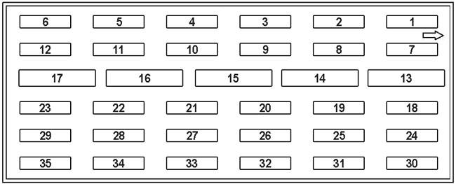
| Pozycja | Amperaż [A] | Chroniony obwód / funkcja |
|---|---|---|
| 1 | 7,5 | Right low-beam headlamp |
| 2 | 15 | Front cigarette lighter and glovebox lamp; radio until September 1993 |
| 3 | 10 | Heating / climate control, radio and warning circuits |
| 4 | 15 | Turn indicators and hazard lights, instrument cluster and timer depending on version |
| 5 | 20 | Radio, heater / air conditioning and horn depending on equipment |
| 6 | 7,5 | Turn indicators and trailer wiring |
| 7 | 7,5 | Left low-beam headlamp |
| 8 | 7,5 | Heated rear-window control |
| 9 | 7,5 | Cigarette lighter, number-plate and instrument illumination |
| 10 | – | Spare position |
| 11 | 7,5 | Air conditioning / auxiliary fan control |
| 12 | 10 | Brake lights and braking signal for ABS, ASR, ASD and cruise control |
| 13 | 30 | Auxiliary fan speed 1 / 2 |
| 14 | 30 | Blower motor and blower regulator |
| 15 | 30 | Windscreen wipers and washer, combination switch and selected lighting circuits |
| 16 | 30 | Heated rear window / combined relay |
| 17 | 40 | M104 HFM-SFI secondary air injection pump |
| 18 | 7,5 | Left parking / side lights and left rear lamp |
| 19 | 7,5 | Right high-beam headlamp |
| 20 | 10 | Heated seats, radio or rear-window sunshade depending on specification |
| 21 | 7,5 / 20 | Automatic aerial or radio depending on version |
| 22 | 10 | Front fog lamps |
| 23 | 15 | Diagnostics, overvoltage protection relay, heating and selected engine controls |
| 24 | 10 | Right parking / side lights, trailer wiring and headlamp washers |
| 25 | 7,5 | Left high beam and its indicator |
| 26 | 7,5 | Telephone, comfort electronics and SRS warning lamp depending on specification |
| 27 | 7,5 | Door courtesy lights or diagnostic connector depending on market |
| 28 | 7,5 | Rear fog lamp / trailer system |
| 29 | 15 | Heated mirrors and washer jets, reversing lamps and starter interlock |
| 30 | 10 | Headlamp washer / wiper systems |
| 31 | – | Spare position |
| 32 | 7,5 | Diagnostic module II on selected markets |
| 33 | 15 | Interior and boot lighting, central locking |
| 34 | 7,5 / 10 | Folding mirrors, rear headrest release and daytime running lights, version dependent |
| 35 | 7,5 / 15 | Central locking, alarm, cabin lighting and trailer module, version dependent |
Engine compartment – 1 December 1994 to 31 May 1997
Mercedes used closely related diagrams for December 1994-August 1996 and September 1996-May 1997. Both illustrations are shown to support identification. The associated listing includes spare positions and equipment-dependent ratings; notably F14 (15 A) is the documented front lighter position.
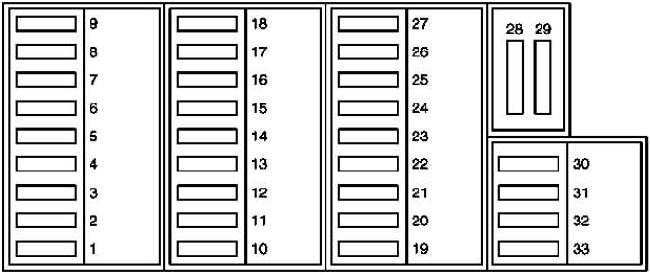

| Pozycja | Amperaż [A] | Chroniony obwód / funkcja |
|---|---|---|
| 1 | 7,5 | Turn indicators and trailer wiring |
| 2 | 15 / 20 | Horn, heater / climate control and recirculation depending on equipment |
| 3 | 7,5 / 10 / 15 | Instrument cluster, stop lamps, ABS/ASR/ASD and cruise control depending on date |
| 4 | 7,5 / 15 | Right low-beam headlamp |
| 5 | 7,5 | Left low-beam headlamp |
| 6 | 7,5 | Right high-beam headlamp |
| 7 | 7,5 | Left high beam and its indicator |
| 8 | 10 | Front fog lamps |
| 9 | 30 / 40 | Blower motor / regulator |
| 10 | 15 | Hazard warning lights / instrument cluster |
| 11 | 40 | Heated rear window |
| 12 | 10 / 15 / 20 | Heating / air conditioning; cigarette lighter on some versions |
| 13 | 40 | Wiper, washer and rear-window heating via combined relay |
| 14 | 15 | Front cigarette lighter, glovebox lamp and optional equipment |
| 15 | 15 | Right parking / side lights, number plate and cigarette-lighter illumination |
| 16 | 7,5 | Left parking / side lights and left rear lamp |
| 17 | 7,5 | Rear fog lamp |
| 18 | 7,5 / 40 | Air-conditioning blower / fan depending on version |
| 19 | 15 | S202 estate cargo-area power socket |
| 20 | 7,5 | SRS / seatbelt pretensioners / comfort electronics |
| 21 | 15 | Radio, phone or heated seats depending on equipment |
| 22 | 10 | Electric rear-window sunshade |
| 23 | 15 | Interior lighting, alarm, central locking, automatic-dimming mirror and trailer wiring |
| 24 | 15 | Door mirrors, reverse lamps and orthopedic seat back depending on version |
| 25 | 20 | Heated front seats |
| 26 | 15 | Radio / phone |
| 27 | 15 | Interior and luggage lighting, central locking |
| 28 | 40 | Secondary-air injection pump on applicable engines |
| 29 | 30 | Auxiliary fan |
| 30 | 15 / 20 | Engine control, overvoltage or heating relay depending on engine |
| 31 | 10 | Heated washer jets, starter interlock and reversing lights depending on version |
| 32 | 7,5 | Diagnostics / fuel-system components depending on variant |
| 33 | 7,5 | Diagnostic module II on certain markets |
Engine compartment – from 1 June 1997
Later W202 electrical distribution assigns the front cigarette lighter to F23 (15 A). The S202 estate can also have separate rear-wiper and luggage-compartment equipment. PARKTRONIC, ESP, telephone, navigation, xenon lighting and security options influence the fitted circuits.
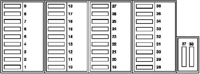
| Pozycja | Amperaż [A] | Chroniony obwód / funkcja |
|---|---|---|
| 1 | 5 | Heated seats, comfort functions and seatbelt systems depending on equipment |
| 2 | 5 | SRS, belt tensioners, impact / seat occupancy sensors |
| 3 | 5 / 15 | Radio, phone and voice control depending on specification |
| 4 | 5 | Instrument cluster / SRS warning indicator |
| 5 | 15 / 20 | Rear sunshade, navigation or S202 boot power outlet depending on version |
| 6 | 7,5 | Folding mirrors, parking / navigation equipment, phone or TELE AID |
| 7 | 7,5 | Lower control panel for mirrors, windows, reverse circuit, boot, telephone and navigation |
| 8 | 30 | Driver door module, power window, mirror and central locking |
| 9 | 25 | Overhead panel for roof, interior lighting, rain sensor and RF receiver |
| 10 | 15 | Radio / phone |
| 11 | 20 | Heated front seats |
| 12 | 25 | Audio system / amplifier |
| 13 | 15 | Xenon headlamp levelling / reverse lamp |
| 14 | 5 | PARKTRONIC or taxi-meter equipment |
| 15 | 15 | S202 rear wiper; brake lights from June 1999 on selected variants |
| 16 | 5 | ESP / steering angle sensor; S202 rear wiper from June 1999 |
| 17 | 30 | Left rear door controller |
| 18 | 25 | Trailer lighting and power supply |
| 19 | 10 | Instrument cluster, lamp monitoring, daytime-running and brake lights |
| 20 | 15 | Heating / air-conditioning controls and sensors |
| 21 | – | Spare position |
| 22 | 10 | Combination switch, wipers, washer and indicators |
| 23 | 15 | Front cigarette lighter and glovebox lamp |
| 24 | 15 | Right parking / side lights, plate lamps and headlamp cleaning |
| 25 | 7,5 | Left parking / side lights |
| 26 | 7,5 | Rear fog lamp |
| 27 | 15 | Electronic steering column lock |
| 28 | 5 / 10 | Cigarette lighter, minibar, taxi-meter or ESP steering angle sensor by date |
| 29 | 30 / 40 | Blower motor / auxiliary fan depending on version |
| 30 | 10 | Heater and climate control, circulation pump and duovalve |
| 31 | 7,5 / 15 | Right low-beam headlamp |
| 32 | 7,5 / 15 | Left low-beam headlamp |
| 33 | 7,5 | Right high-beam headlamp |
| 34 | 7,5 | Left high beam and indicator |
| 35 | 15 | Front fog lamps |
| 36 | – | Spare position |
| 37 | 25 / 40 | Heater booster or ESP pump depending on engine |
| 38 | 30 / 40 / 60 | Auxiliary / electric fan depending on engine and climate control |
Supplementary fuse block F39-F45 on later cars
This block includes horn, rain-sensor, washer and wiper functions. F44 (40 A) is used for the wiper motor, while F40 (10 A) is listed for the horns. Some equipment shares combined control and relay circuitry at F41.
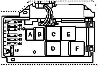
| Pozycja | Amperaż [A] | Chroniony obwód / funkcja |
|---|---|---|
| 39 | – | Spare position |
| 40 | 10 | Horns |
| 41 | 15 | Turn indicators, horn, wiper / washer, rain sensor, heated rear window, fan, headlamp washers and hazard lights |
| 42 | 7,5 | Heated washer fluid / washer system |
| 43 | 7,5 | Windscreen washer pump |
| 44 | 40 | Wiper motor / rain sensor |
| 45 | 15 | Headlamp washing system |
Luggage compartment fuse box – early configuration
The older rear fuse carrier distributes power to electric seat functions, audio, comfort electronics, alarm equipment, the sunroof and optional trailer installations.
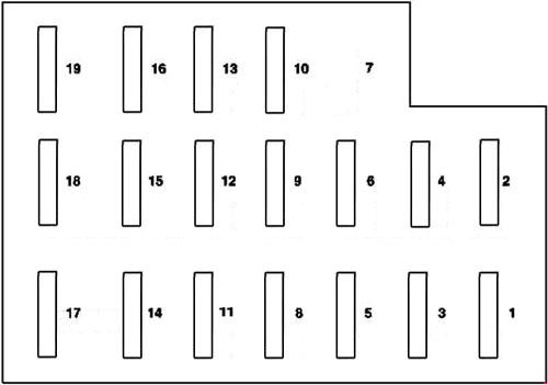
| Pozycja | Amperaż [A] | Chroniony obwód / funkcja |
|---|---|---|
| 1 | 25 | Partial power feed for left front electric seat adjustment |
| 2 | 25 | Partial power feed for right front electric seat adjustment |
| 3 | 25 | Partial power feed for left front electric seat adjustment |
| 4 | 25 | Partial power feed for right front electric seat adjustment |
| 5 | 25 | Audio system / amplifier |
| 6 | 7,5 | CD changer |
| 7 | 30 | Comfort module: rear power windows / sliding roof |
| 8 | 7,5 | Alarm / tilt sensor depending on equipment |
| 9 | 7,5 | Comfort relay / module |
| 10 | 30 | Comfort module: front power windows |
| 11 | 20 | Alarm / siren on selected models |
| 12 | 20 | Heated front seats |
| 13 | 20 | Sliding / tilting sunroof |
| 14-16 | – | Spare positions |
| 17 | 7,5 / 30 | Telephone, depending on version |
| 18 | 25 | Trailer / fuel pump circuit depending on variant |
| 19 | – | Spare position |
Luggage compartment fuse box – from 1 December 1994
The rear wiring changed again from June 1997. In applicable versions, F1 (25 A) became a fuel-pump fuse. F2-F8 also have different functions after this date, so do not mix the early and late assignments.
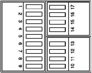
| Pozycja | Amperaż [A] | Chroniony obwód / funkcja |
|---|---|---|
| 1 | 25 | Up to May 1997: audio; from June 1997: fuel pump |
| 2 | 7,5 / 30 | Up to May 1997: comfort system; from June 1997: PSE, central locking and alarm |
| 3 | 20 / 30 | Up to May 1997: alarm; from June 1997: driver’s door control module |
| 4 | 7,5 / 40 | Up to May 1997: electric aerial; from June 1997: PSE, central locking and rear-window heater |
| 5 | 7,5 / 30 | Up to May 1997: entry lighting; from June 1997: rear-door module |
| 6 | 25 / 5 | Up to May 1997: trailer; from June 1997: rear / boot / seat lighting |
| 7 | 30 / 5 | Up to May 1997: rear windows; from June 1997: alarm |
| 8 | 30 / 10 | Up to May 1997: front windows; from June 1998: TELE AID / eCall by market |
| 9 | 20 | Up to May 1997: sunroof; later configuration-dependent |
| 10 | 25 | Left front seat – partial adjustment supply |
| 11 | 25 | Left front seat – partial adjustment supply |
| 12 | 25 | Right front seat – partial adjustment supply |
| 13 | 25 | Right front seat – partial adjustment supply |
| 14-17 | – | Spare positions / optional equipment |
Main relay box positions
The lettered positions refer to relay modules rather than blade fuses. The combined relay controls several systems; a fault in more than one circuit should prompt checks beyond a single fuse.
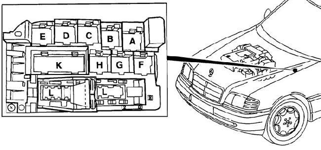
| Pozycja | Amperaż [A] | Chroniony obwód / funkcja |
|---|---|---|
| A | – | Downstream oxygen sensor heater relay, on relevant versions |
| B | – | ASR or secondary-air system, depending on engine and model year |
| C | – | Auxiliary fan speed 1 relay |
| C+D | – | Auxiliary fan speeds 1 / 2 on early models |
| D | – | Auxiliary fan speed 2 relay |
| E | – | HCS module, where fitted |
| F | – | Horn relay |
| G | – | Daytime running light relay on selected markets |
| H | – | High-pressure / return-pump relay depending on version |
| K | – | Combined relay for indicators, hazard lights, heated rear window and wipers |
| L | – | Exterior lamp failure monitoring module |
M111 engine relay and module identification
On applicable M111 engines, relay K27 is associated with the fuel pump and connector X11/4 is a diagnostic connection. The exact fitted control system and emissions equipment can differ.
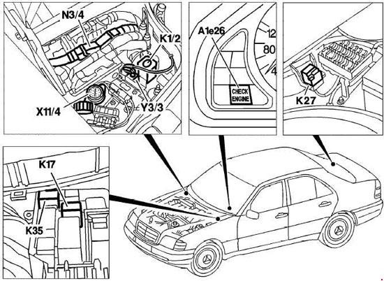
| Pozycja | Amperaż [A] | Chroniony obwód / funkcja |
|---|---|---|
| A1e26 | – | CHECK ENGINE / malfunction indicator lamp (MIL) |
| K1/2 | – | Overvoltage protection relay module |
| K17 | – | Secondary air injection relay module |
| K27 | – | Fuel pump relay |
| K35 | – | Downstream oxygen sensor heater relay |
| N3/4 | – | HFM-SFI engine control unit |
| X11/4 | – | Diagnostic connector |
| Y3/3 | – | Idle-speed gear-change delay valve |
Practical troubleshooting notes
Cigarette lighter has no power: first identify the production period. Check F2 (until November 1994), F14 (December 1994-May 1997) or F23 (from June 1997), all listed at 15 A. Wipers not working: the documented protection moves between F15, F13 and the late supplementary F44.
Fuel pump failure on a later car: inspect the relevant rear-box F1 (25 A) and the fuel-pump relay / control circuit where fitted. One fuse repeatedly blows: investigate the circuit rather than substituting a higher rating. Always use the installed fuse card and correct amperage for the vehicle.