
Mercedes-Benz GLC X253 (2015-2022) and GLC Coupe C253 (2016-2023) are the first-generation GLC SUV and coupe. The fuse and relay system includes a rear SAM in the luggage compartment, a front passenger footwell fuse box, a dashboard side panel, engine-compartment fuses, and separate high-current protection assemblies.
Fuse locations and functions depend on the build date, market, engine and equipment such as BlueTEC / AdBlue, GLC 350 e Hybrid, AIR BODY CONTROL and driver assistance. These complete charts keep spare positions, relay identification and equipment-dependent fuse assignments. Always check the vehicle’s own fuse assignment chart before replacing a fuse.
Where are the fuse boxes in Mercedes GLC X253/C253?
Luggage compartment: switch the ignition off, open the tailgate and remove or fold back the relevant rear luggage trim access cover. The rear SAM fuse and relay unit is under the protective cover. It supplies the rear window, power sockets, fuel-system control, powered tailgate and other rear vehicle electronics.
Front passenger footwell: move the front passenger seat rearwards and remove the designated lower trim / footwell service cover. The box contains the F301-F323 positions and smaller MF1/MF2/MF3 groups. Do not interfere with nearby SRS wiring while opening the panel.
Dashboard: the F200-F220 fuse panel is behind a side dashboard access cover at the front A-pillar area. Dashboard trim access may differ by left- or right-hand-drive specification.
Engine compartment: open the bonnet and locate the covered main fuse and relay housing. A separate high-current pre-fuse carrier protects large loads and main distribution branches. These high-current links should only be inspected or serviced using the specified vehicle electrical isolation procedure.
The related Mercedes C-Class W205 shares some electrical architecture, but its fuse assignments cannot be substituted automatically for the GLC.
Frequently checked fuses in Mercedes GLC
This quick reference lists the most commonly requested 12 V and accessory circuits. The full tables below distinguish all model-specific options and relay positions.
| Pozycja | Amperaż [A] | Chroniony obwód / funkcja |
|---|---|---|
| F446 | 15 | Front cigarette lighter / 12 V outlet |
| F447 | 15 | Rear centre console 12 V outlet |
| F445 | 15 | Luggage compartment 12 V outlet |
| F442 | 25 | Fuel system controller |
| F109 | 30 | Front windscreen wiper motor |
| F322 | 20 | Audio / COMAND head unit |
| F204 | 5 | OBD diagnostic socket |
| F463 | 30 | Heated rear window |
Rear SAM fuse and relay box, F400-F467
The rear carrier has at least two documented physical arrangements. Use the installed rear SAM diagram and equipment chart. The full listing covers BlueTEC AdBlue, Hybrid, trailer control, electric seats, camera electronics, KEYLESS-GO, audio and cabin power sockets.
Rear layout variant 1

Rear layout variant 2

| Pozycja | Amperaż [A] | Chroniony obwód / funkcja |
|---|---|---|
| 400 | 25 | BlueTEC AdBlue controller |
| 401 | 15 | BlueTEC AdBlue controller |
| 402 | 20 | BlueTEC AdBlue controller |
| 403 | 30 / 25 | Part-electric passenger seat: 30 A through 30 November 2015; 25 A from 1 December 2015 |
| 404 | 30 / 25 | Part-electric driver seat: 30 A through 30 November 2015; 25 A from 1 December 2015 |
| 405 | – | Spare / unoccupied position |
| 406 | 30 | Left front door controller |
| 407 | – | Spare / unoccupied position |
| 408 | 30 | Right rear door controller |
| 409 | – | Spare / unoccupied position |
| 410 | 5 | Parking heater remote receiver / telephone and auxiliary heater antenna changeover |
| 411 | 30 | Left front reversible seat belt pretensioner |
| 412 | 7.5 | Hybrid battery management control module |
| 413 | 5 | Boot lid / powered tailgate controller |
| 414 | 5 | Tuner |
| 415 | 5 | Camera cover control / AIR-BALANCE fragrance generator |
| 416 | 7.5 | Telephone antenna compensator and contact plate |
| 417 | 5 | 360-degree camera / reversing camera controller |
| 418 | 5 | Rear seat heating module; AIRSCARF assignment from shared platform documentation does not normally apply to GLC |
| 419 | 5 | Front passenger lumbar support controller |
| 420 | 5 | Driver lumbar support controller |
| 421 | – | Spare / unoccupied position |
| 422 | – | Spare / unoccupied position |
| 423 | 5 | Audio amplifier controller |
| 424 | 15 | AIR BODY CONTROL Plus; M276 engine sound controller |
| 425 | – | Spare / unoccupied position |
| 426 | – | Spare / unoccupied position |
| 427 | – | Spare / unoccupied position |
| 428 | – | Spare / unoccupied position |
| 429 | – | Spare / unoccupied position |
| 430 | – | Spare / unoccupied position |
| 431 | 25 | Special-purpose vehicle controller |
| 432 | 25 | Special-purpose vehicle controller |
| 433 | 20 | Trailer recognition module |
| 434 | 30 | Trailer recognition module |
| 435 | 25 | Trailer recognition module |
| 436 | 15 | Trailer recognition module |
| 437 | 25 | Trailer recognition module |
| 438 | 30 | DC/AC inverter |
| 439 | – | Spare / unoccupied position |
| 440 | 30 | Rear seat heating controller; AIRSCARF platform entry does not normally apply to GLC |
| 441 | 30 | AIRSCARF platform position, normally unused in GLC |
| 442 | 25 | Fuel system controller |
| 443 | 30 | Right front reversible seat belt pretensioner |
| 444 | 15 | Tablet PC power interface, if equipped |
| 445 | 15 | Luggage compartment 12 V outlet |
| 446 | 15 | Front cigarette lighter / cabin 12 V outlet |
| 447 | 15 | Right rear centre console 12 V outlet |
| 448 | 10 | 722/725 transmission parking pawl capacitor circuit |
| 449 | 5 | OM626 diesel fuel filter heater; Hybrid sound generator |
| 450 | 5 | Rear SAM module |
| 451 | 5 | Fuel system controller or BlueTEC AdBlue controller |
| 452 | 5 | Rear radar sensors |
| 453 | 5 | Front radar sensors / COLLISION PREVENTION ASSIST |
| 454 | 7.5 / 5 | Transmission 722 VGS integrated controller at 7.5 A; BlueTEC AdBlue at 5 A |
| 455 | 5 | DC/AC inverter controller |
| 456 | 5 | Front long-range radar / DISTRONIC |
| 457 | 5 | Hybrid power electronics and DC/DC converter |
| 458 | 5 | Rear switching module |
| 459 | 5 | Hybrid charger |
| 460 | 10 | KEYLESS-GO controller |
| 461 | 5 | FM/AM, central locking and KEYLESS-GO aerial amplifier |
| 462 | 40 | Audio system amplifier |
| 463 | 30 | Heated rear window |
| 464 | 40 | Boot lid / electric tailgate module |
| 465 | 40 | Rear SAM module |
| 466 | 40 | Rear SAM module |
| 467 | 40 | OM626 diesel fuel filter heater |
Rear fuse box relays S-ZR3
| Pozycja | Amperaż [A] | Chroniony obwód / funkcja |
|---|---|---|
| S | – | Interior circuit 15 relay |
| T | – | Heated rear-window relay |
| U | – | Cupholder / second-row 12 V socket relay |
| V | – | BlueTEC AdBlue relay |
| X | – | First-row and luggage-compartment 12 V socket relay |
| Y | – | Spare relay |
| ZR1 | – | OM626 fuel filter heater relay |
| ZR2 | – | Spare relay |
| ZR3 | – | Spare relay |
Front cigarette lighter: F446 (15 A); rear console socket: F447 (15 A); luggage compartment socket: F445 (15 A). The fuel-system controller uses F442 (25 A). BlueTEC AdBlue control is protected by F400-F402 on applicable diesels.
Front passenger footwell fuse box F301-F323 and MF groups
This fuse box supplies door and seat modules, DIRECT SELECT, cameras, radar systems, the Audio/COMAND head unit, auxiliary heating, AIR BODY CONTROL and equipment-specific Hybrid controls. The MF mini-fuse groups remain part of the complete table.
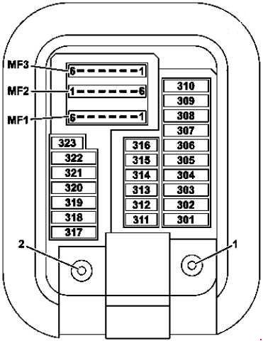
| Pozycja | Amperaż [A] | Chroniony obwód / funkcja |
|---|---|---|
| 301 | 5 | Hybrid pyrotechnic safety disconnector / high-voltage isolation circuit |
| 302 | 30 | Right front door controller |
| 303 | 30 | Left rear door controller |
| 304 | 20 | 722 transmission DIRECT SELECT servo module |
| 305 | 30 | Driver seat / seat heating controller |
| 306 | 30 | Front passenger seat / seat heating controller |
| 307 | – | Spare / unoccupied position |
| 308 | 30 | USA: electric trailer brake connector |
| 309 | 10 / 5 | eCall control module 10 A, or HERMES telematics 5 A |
| 310 | – | Spare / unoccupied position |
| 311 | 10 | Auxiliary heater blower regulator |
| 312 | 10 | Overhead control panel |
| 313 | 10 | Hybrid DC/DC converter controller |
| 314 | – | Spare / unoccupied position |
| 315 | 5 | Powertrain controller: CDI diesel or ME-SFI petrol |
| 316 | 7.5 | Supplementary SRS control module |
| 317 | 30 | Panoramic / sliding roof controller |
| 318 | 20 | Parking heater controller |
| 319 | 5 | Hybrid high-voltage PTC heater |
| 320 | 15 | AIR BODY CONTROL controller |
| 321 | 5 | Japan DSRC communications controller |
| 322 | 20 | Audio / COMAND head unit |
| 323 | 5 | Parking assistance controller |
| MF1/1 | 7.5 | Audio / COMAND display and audio cooling fan |
| MF1/2 | 7.5 | Mono / stereo multifunction camera |
| MF1/3 | 7.5 | Rain and light sensor, overhead control panel |
| MF1/4 | 7.5 | Driver seat / seat heating controller |
| MF1/5 | 7.5 | Passenger seat / seat heating controller |
| MF1/6 | 7.5 | Steering column control module |
| MF2/1 | 5 | Left front reversible seatbelt pretensioner |
| MF2/2 | 5 | Audio / COMAND control panel and touchpad |
| MF2/3 | 5 | Right front reversible seatbelt pretensioner |
| MF2/4 | 5 | Head-up display |
| MF2/5 | 5 | Multimedia interface |
| MF2/6 | 5 | Hybrid electric air conditioning compressor |
| MF3/1 | 5 | Terminal 30g supply / front SAM |
| MF3/2 | 5 | Radar sensor controller |
| MF3/3 | – | Spare / unoccupied position |
| MF3/4 | 5 | Driver-side dashboard switch assembly |
| MF3/5 | 5 | Rear climate control unit |
| MF3/6 | 5 | Tyre pressure monitoring unit |
Dashboard fuse panel F200-F220
The dashboard panel contains the front SAM supply, electronic ignition switch, instrument panel, air conditioning, SRS and passenger seat occupancy detection. Spare and market-specific positions are retained.
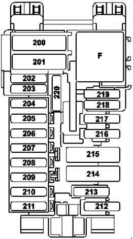
| Pozycja | Amperaż [A] | Chroniony obwód / funkcja |
|---|---|---|
| 200 | 50 | Front SAM module |
| 201 | 40 | Front SAM module |
| 202 | 5 | Alarm siren |
| 203 | 20 | Transmission 716 electric steering-column lock |
| 204 | 5 | OBD diagnostic connector |
| 205 | 7.5 | Electronic ignition switch (EIS) |
| 206 | 5 | Analogue clock |
| 207 | 15 | Climate control unit |
| 208 | 7.5 | Instrument cluster |
| 209 | 5 | Climate control / overhead control panel |
| 210 | 10 | Steering-column control module |
| 211 | 25 | Spare or model-dependent position |
| 212 | 5 | Spare or model-dependent position |
| 213 | 5 | ESP controller |
| 214 | 30 | Spare or model-dependent position |
| 215 | – | Spare / unoccupied position |
| 216 | 7.5 | Glovebox lighting |
| 217 | 5 | Japan DSRC communication unit |
| 218 | 7.5 | Additional SRS controller |
| 219 | 5 | Passenger seat weight / occupancy sensor (WSS) |
| 220 | – | Spare / unoccupied position |
Dashboard relay position F
| Pozycja | Amperaż [A] | Chroniony obwód / funkcja |
|---|---|---|
| F | – | Circuit 15R relay |
Engine compartment fuse box F100-F129A
Engine fuse positions vary by diesel or petrol engine, Hybrid configuration and equipment. For example F107 (60 A) supplies the electric coolant pump on M274.9; F109 (30 A) protects the front windscreen wiper motor. LED headlamp protection is listed at F108 and F110; not all headlamp variants are wired identically.

| Pozycja | Amperaż [A] | Chroniony obwód / funkcja |
|---|---|---|
| 100 | 40 | Hybrid vacuum pump |
| 101 | 15 | Circuit 87/2 connection |
| 102 | 20 | Circuit 87/1 connection |
| 103 | 15 | Circuit 87/4 connection |
| 104 | 15 | Circuit 87/3 connection |
| 105 | 15 | 722.9 automatic transmission auxiliary oil pump controller, except 722.930 |
| 106 | – | Spare / unoccupied position |
| 107 | 60 | M274.9 electric coolant pump |
| 108 | 20 | LED headlights: right or both, dependent on lighting version |
| 109 | 30 | Front windscreen wiper motor |
| 110 | 20 | LED headlights: left or both, dependent on lighting version |
| 111 | 30 | Starter motor |
| 112 | 15 | Hybrid accelerator pedal position sensor |
| 113 | – | Spare / unoccupied position |
| 114 | 40 | AIR BODY CONTROL compressor |
| 115 | 15 | Left and right horns |
| 116 | – | Spare / unoccupied position |
| 117 | – | Spare / unoccupied position |
| 118 | 5 | Hybrid ESP controller |
| 119 | 15 | Circuit 87 C1 / C2 connection, version dependent |
| 120 | 5 | Circuit 87 C1 / C2 connection, version dependent |
| 121 | 5 | ESP controller |
| 122 | 5 | CPC relay |
| 123 | – | Spare / unoccupied position |
| 124 | – | Spare / unoccupied position |
| 125 | 5 | Front SAM |
| 126 | 5 | Powertrain control unit: CDI diesel or ME-SFI petrol |
| 127 | 5 | Hybrid voltage drop limiter |
| 128 | 5 | Left headlamp and exterior light switch |
| 129 | 30 | Hybrid starter terminal 50 relay |
| 129A | 30 | Hybrid starter terminal 50 relay |
Engine-bay relays G-R
| Pozycja | Amperaż [A] | Chroniony obwód / funkcja |
|---|---|---|
| G | – | Engine compartment terminal 15 relay |
| H | – | Starter terminal 50 relay |
| I | – | Hybrid vacuum pump positive relay |
| J | – | CPC relay |
| K | – | Transmission 722.9 oil pump relay |
| L | – | Horn relay |
| M | – | Wiper resting-position heater relay |
| N | – | Circuit 87M relay |
| O | – | Hybrid starter terminal 15 relay |
| P | – | M274.9 coolant pump relay |
| Q | – | Hybrid vacuum pump negative relay |
| R | – | AIR BODY CONTROL relay |
Engine compartment high-current pre-fuse box
Two different original drawings cover the front high-current fuse block. They include alternator protection, electric steering, radiator cooling, main SAM feeds, diesel glow-plug power and Hybrid distribution. Do not treat its high-current fuses as interchangeable with ordinary passenger-compartment blade fuses.
Front pre-fuse version 1
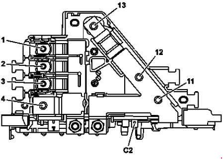
Front pre-fuse version 2
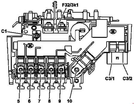
| Pozycja | Amperaż [A] | Chroniony obwód / funkcja |
|---|---|---|
| 1 | – | Spare / unoccupied position |
| 2 | 100 | Diesel glow plug controller |
| 3 | 60 | Engine fuse and relay module |
| 4 | – | Vehicle battery connection to electrical distribution |
| 5 | 150 | Engine fuse and relay module |
| 6 | 125 | Left-side fuse and relay module |
| 7 | 80 | 600 / 850 W engine cooling fan motor |
| 8 | 125 | Electric power steering controller |
| 9 | 150 | 1000 W cooling fan motor |
| 10 | 200 | Interior high-current fuse block |
| 11 | – | Spare / unoccupied position |
| 12 | – | Hybrid power electronics; OM651.9 USA catalyst heater controller |
| 13 | 400 | Alternator |
| C1 | – | Hybrid isolation relay |
| C2 | – | Hybrid terminal 31 circuit |
| C3/1 | 40 | ESP controller |
| C3/2 | 60 | ESP controller |
Interior high-current fuse distribution
The internal main block feeds the passenger blower, diesel PTC heater, A-pillar and rear fuse modules and the transmission. In the documented configuration, position 10 is 60 A for the 725 transmission VGS, but 100 A on GLC 350 e 4MATIC.

| Pozycja | Amperaż [A] | Chroniony obwód / funkcja |
|---|---|---|
| 1 | – | Connection to engine-compartment high-current fuse block |
| 2 | 150 | Hybrid auxiliary battery for ECO start-stop |
| 3 | 40 | Heater blower regulator |
| 4 | – | Spare / unoccupied position |
| 5 | 150 | Diesel electric PTC heater |
| 6 | 80 | Right A-pillar fuse box |
| 7 | 150 | Rear fuse and relay module |
| 8 | – | Spare / unoccupied position |
| 9 | – | Spare / unoccupied position |
| 10 | 60 / 100 | Transmission 725 VGS controller 60 A; GLC 350 e 4MATIC 100 A |
| 11 | – | Spare / unoccupied position |
| 12 | 40 | Rear fuse and relay module |
| 13 | 50 | Right A-pillar fuse box |
Practical troubleshooting for GLC electrical faults
12 V socket has no power: check the correct rear SAM fuse F445, F446 or F447. Remove chargers and inspect the socket for conductive debris before installing a replacement.
Front wipers do not operate: inspect engine-bay F109 (30 A) and the wiper mechanism. Heated rear window does not work: check F463 (30 A) and rear relay T.
Fuel delivery fault: the fuel-system controller uses rear F442 (25 A). A good fuse does not eliminate faults in the controller, pump or associated wiring.
AIR BODY CONTROL warning: inspect engine-bay F114 (40 A), the matching compressor relay R and the footwell control supply as applicable, then test for compressor overload or air leakage. Do not raise fuse amperage to hide an underlying problem.
Hybrid GLC 350 e: these cars contain additional high-voltage electronics, isolation and charging systems. High-voltage components must not be inspected or repaired using standard 12 V fuse procedures. The assigned fuse card and manufacturer’s electrical safety instructions take precedence for every installation.