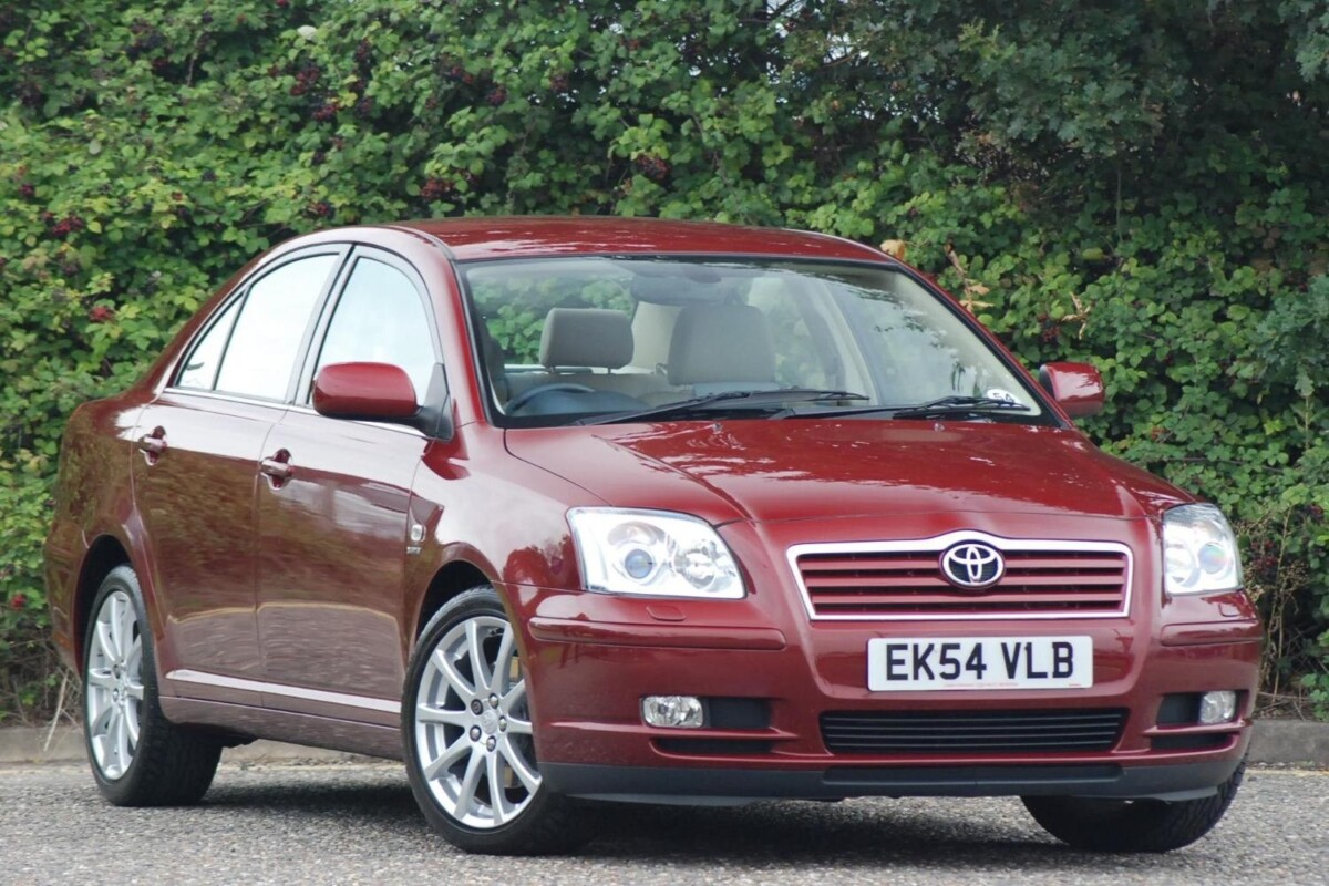
Toyota Avensis II T25 (2003-2009) uses different fuse and relay arrangements depending on its petrol or diesel engine, production year and installed equipment. The range includes petrol 3ZZ-FE, 1ZZ-FE, 1AZ-FE, 1AZ-FSE and 2AZ-FSE and diesel 1CD-FTV, 1AD-FTV, 2AD-FTV and 2AD-FHV, with optional VSC, headlamp washers, PTC heating and D-CAT emissions equipment.
The early engine-bay layout is not interchangeable with the later 2007 manual arrangement. The supplementary interior fuse panel also changes position numbering. All original fuse codes, alternative amperages, empty positions, relays and LHD/RHD distinctions are preserved below. Check the diagram on the installed fuse cover and the vehicle’s own owner’s manual before replacing a fuse.
Where are the fuses in Toyota Avensis T25?
Driver-side dashboard: switch off the ignition, locate the lower dashboard service cover beside the driver’s footwell and carefully remove it to reach the main junction block. A second, smaller fuse carrier can be installed higher near the pedal / dashboard wiring area. In right-hand-drive models the layout and some relay and window positions differ.
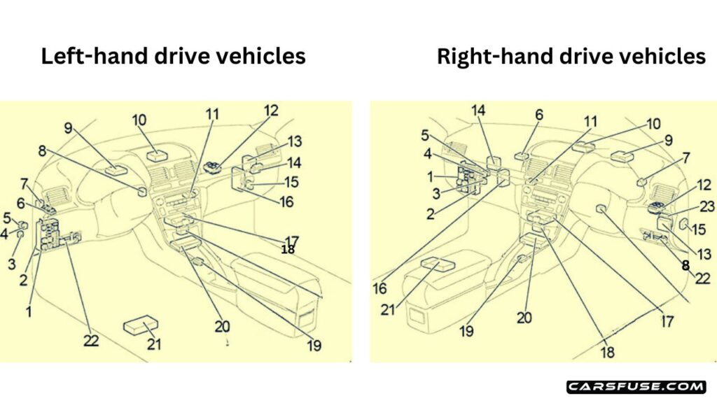
Engine compartment: the covered main fuse and relay box is on the left side of the bay. Release its retaining clips with the vehicle switched off. Petrol and diesel models can have different supplementary blocks for glow plugs, alternator power, PTC heater, ABS/VSC and headlamp cleaning. Never replace a large fusible link by bridging it with wire.
Common fuses: lighter, sockets, OBD, wipers and radio
The original cigar lighter is protected by CIG, position 9, 15 A in the main cabin box. The additional 12 V outlet is P/POINT, position 16, 15 A. A factory Avensis T25 has no dedicated USB fuse; any retrofit USB module needs its own wiring checked.
| Pozycja | Amperaż [A] | Chroniony obwód / funkcja |
|---|---|---|
| CIG | 15 | Cigarette lighter. main cabin fuse panel position 9 |
| P/POINT | 15 | Additional 12 V socket. main cabin panel position 16 |
| OBD2 | 7.5 | OBD diagnostic port. main cabin panel position 15 |
| RAD NO.1 | 7.5 | Radio/audio. main cabin panel position 12 |
| RAD NO.2 | 15 | Radio. display and navigation. early auxiliary panel position 13 or 2007 panel position 5 |
| WIP | 25 | Front wipers and washer. main cabin panel position 18 |
| RR WIP | 20 | Rear wiper and washer. main cabin panel position 7 |
| STOP | 15 | Brake lights. main cabin panel position 22 |
| FR FOG | 15 | Front fog lamps. main cabin panel position 4 |
| RR FOG | 7.5 | Rear fog lamp. main cabin panel position 3 |
| S-HTR | 20 | Heated seats. main cabin panel position 20 |
| DOOR | 25 | Central locking. main cabin panel position 17 |
| MIR HTR | 10 | Heated mirrors. auxiliary panel position 12 early / position 4 on 2007 layout |
| FUEL OPN | 10 | Fuel filler flap release. auxiliary panel position 7 early / position 15 on 2007 layout |
| HORN | 15 | Horn. engine compartment |
| RR DEF | 30 | Heated rear window. engine compartment |
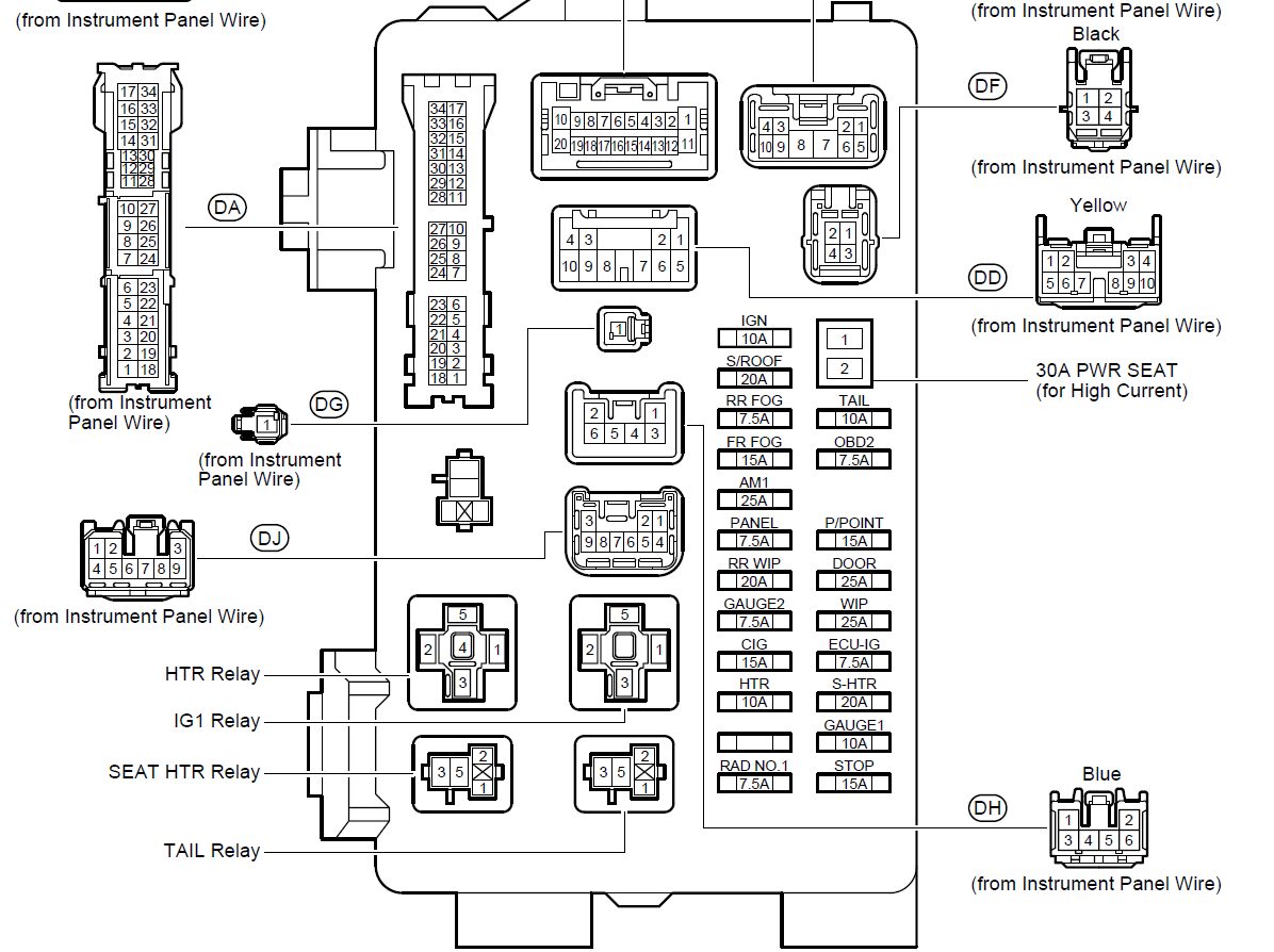
Main passenger compartment junction block – 22 positions
This main panel includes the 25 A WIP windscreen wiper fuse, OBD2 diagnostics, CIG, P/POINT, door locking, dashboard power and heated seat circuits. The 30 A PWR SEAT position is for an electric seat, not the accessory socket. Position 11 is deliberately unused in this table.
| Pozycja | Amperaż [A] | Chroniony obwód / funkcja |
|---|---|---|
| 1 | 10 | IGN: SRS. instrument panel. starting. fuel injection and engine control |
| 2 | 20 | S/ROOF: Electric sunroof where fitted |
| 3 | 7.5 | RR FOG: Rear fog lamp |
| 4 | 15 | FR FOG: Front fog lamps and indicator |
| 5 | 25 | AM1: Starting circuit and supply for CIG and RAD NO.1 branches |
| 6 | 7.5 | PANEL: Instrument illumination. display. transmission controls. glovebox and console lights. lighting and parking functions |
| 7 | 20 | RR WIP: Rear window wiper and washer |
| 8 | 7.5 | GAUGE2: Reverse lights. headlamp levelling. turn indicators and hazard warning |
| 9 | 15 | CIG: Cigarette lighter |
| 10 | 10 | HTR: Heater / air conditioning and seat heating |
| 11 | – | Unused position |
| 12 | 7.5 | RAD NO.1: Audio. display. electric mirrors. dashboard and power socket |
| 13 | 30 | PWR SEAT: Power-adjustable seat. where fitted |
| 14 | 10 | TAIL: Parking and tail lamps. number plate and boot lighting. automatic lights. fog lights and dashboard |
| 15 | 7.5 | OBD2: On-board diagnostics |
| 16 | 15 | P/POINT: Additional 12 V socket |
| 17 | 25 | DOOR: Central locking |
| 18 | 25 | WIP: Front wiper and washer. headlamp washer on applicable models |
| 19 | 7.5 | ECU-IG: Cooling fans. charging. ABS. VSC and electric power steering |
| 20 | 20 | S-HTR: Heated seats |
| 21 | 10 | GAUGE1: Display. integration relay. instrument cluster. shift lock. automatic transmission. auto-dimming mirror and parking brake |
| 22 | 15 | STOP: Stop lamps. high-level brake light. ABS. shift lock and engine controller |
Additional passenger fuse box – two different configurations
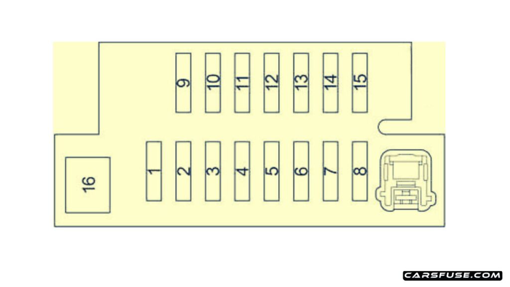
The early panel locates four power-window fuses at positions 2-5. On the later 2007 left-hand-drive panel those fuses are at positions 10-13. The mirror heater, audio, fuel flap, roof and starting feeds can likewise use different positions.
Early auxiliary panel
| Pozycja | Amperaż [A] | Chroniony obwód / funkcja |
|---|---|---|
| 1 | – | Unused position |
| 2 | 20 | P-RR P/W: Right rear power window |
| 3 | 20 | P-FR P/W: Right front power window |
| 4 | 20 | D-RR P/W: Left rear power window |
| 5 | 20 | D-FR P/W: Left front power window |
| 6 | 7.5 | ECU-B 1: Body electronics. including MultiMode gearbox on selected cars |
| 7 | 10 | FUEL OPN: Electric fuel filler flap release |
| 8 | 20 | FR DIC: Front windscreen wiper de-icer and MIR HTR supply |
| 9 | – | Unused position |
| 10 | 7.5 | DEF I/UP: Air conditioning |
| 11 | 7.5 | ST: Starting system. dashboard display and engine controls |
| 12 | 10 | MIR HTR: Heated exterior mirrors |
| 13 | 15 | RAD NO.2: Audio system and display |
| 14 | 7.5 | DOME: Cabin. door. boot. footwell and mirror lighting |
| 15 | 7.5 | ECU-B 2: Air conditioning and remote central locking |
| 16 | 30 | PWR SEAT: Electric seat adjustment |
Left-hand-drive panel from the 2007 manual
At position 9, A/F (15 A) feeds the Toyota D-CAT DPNR system or applicable 1AD-FTV DPR equipment. Other specified engines may not use it. The right-hand-drive window fuse order is not identical to the LHD panel, so a UK-imported Avensis requires its own fuse cover legend.
| Pozycja | Amperaż [A] | Chroniony obwód / funkcja |
|---|---|---|
| 1 | – | Not assigned in the factory manual |
| 2 | 7.5 | DEF I/UP: Air conditioning |
| 3 | 7.5 | ST: Starting system. multi-information display and engine controls |
| 4 | 10 | MIR HTR: Heated exterior mirrors |
| 5 | 15 | RAD NO.2: Audio. navigation and multi-information display |
| 6 | 7.5 | DOME: Interior. door. boot. mirror. footwell and ignition lighting |
| 7 | 7.5 | ECU-B: Remote central locking and air conditioning |
| 8 | 30 | PWR SEAT: Electric seat adjustment on equipped cars |
| 9 | 15 | /F: D-CAT DPNR or 1AD-FTV DPR emissions system; unused in other documented engines |
| 10 | 20 | P-RR P/W: Right rear power window |
| 11 | 20 | P-FR P/W: Right front power window |
| 12 | 20 | D-RR P/W: Left rear power window |
| 13 | 20 | D-FR P/W: Left front power window |
| 14 | 7.5 | ECU-B 1: Unassigned in the 2007 factory fuse chart |
| 15 | 10 | FUEL OPN: Electric fuel filler flap release |
| 16 | 20 | FR DIC: Wiper de-icer and MIR HTR fuse feed |
Interior relays
The main junction block and supplementary relay area contain heater, ignition, heated seats, position lamps, front windscreen de-icer, power outlet, fog lamps and starter relays. These are listed with their short original R-position codes.
| Pozycja | Amperaż [A] | Chroniony obwód / funkcja |
|---|---|---|
| Główny panel | – | Main cabin junction block – unused relay position (Główny panel) |
| Główny panel | – | Main cabin junction block – heater / climate relay (Główny panel) |
| Główny panel | – | Main cabin junction block – heated front seat relay (Główny panel) |
| Główny panel | – | Main cabin junction block – ignition relay (Główny panel) |
| Główny panel | – | Main cabin junction block – parking and rear lighting relay (Główny panel) |
| Dodatkowy blok | – | Supplementary cabin relay box – front wiper de-icer (Dodatkowy blok) |
| Dodatkowy blok | – | Supplementary cabin relay box – accessory 12 V power outlet (Dodatkowy blok) |
| Dodatkowy blok | – | Supplementary cabin relay box – front fog lights (Dodatkowy blok) |
| Dodatkowy blok | – | Supplementary cabin relay box – starter (Dodatkowy blok) |
Early engine compartment fuse box – petrol and 1CD-FTV diesel
Older service diagrams use physical positions 1-27. On certain slots the engine or VSC equipment determines the amp value and protected circuit. Both ABS-only and ABS/VSC alternatives are retained.
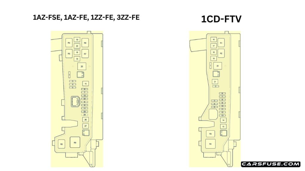
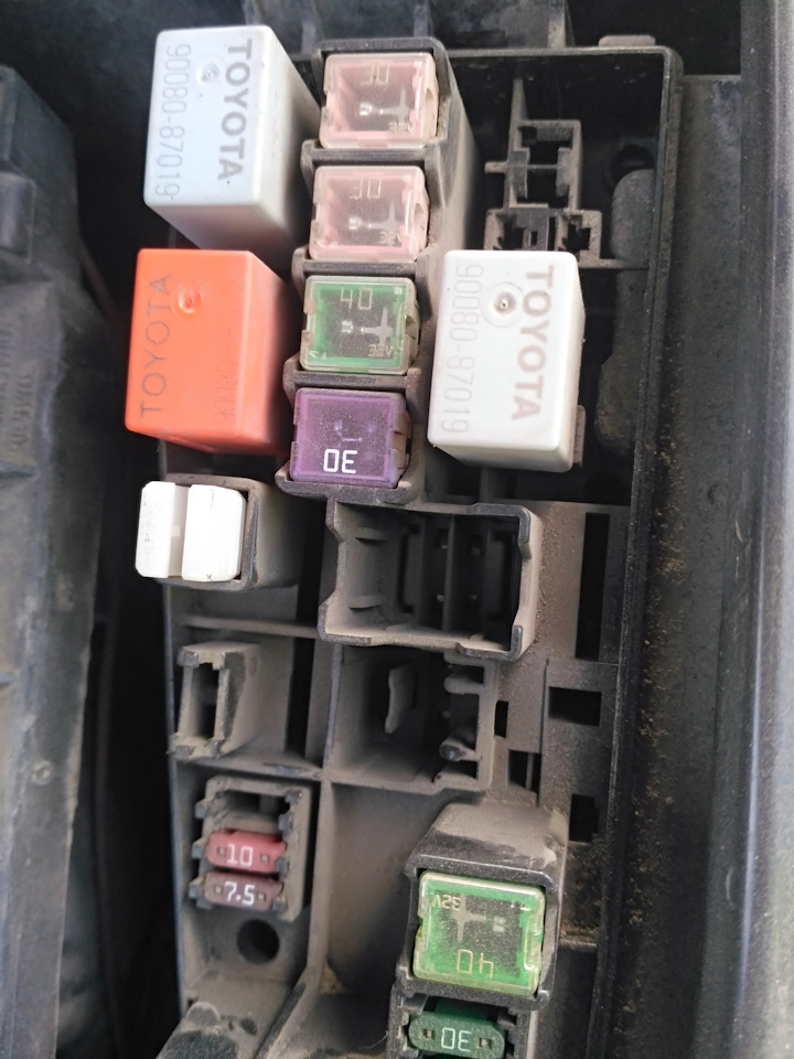
| Pozycja | Amperaż [A] | Chroniony obwód / funkcja |
|---|---|---|
| 1 | – | Unused position |
| 2 | 25 | VSC: 1CD-FTV with VSC: ABS and stability control |
| 2 | 25 | ABS: 1CD-FTV without VSC: ABS |
| 3 | – | Unused position |
| 4 | – | Unused position |
| 5 | – | Unused position |
| 6 | 7.5 | ALT-S: Charging system |
| 7 | 30 | DCC: ECU-B NO.2. DOME and RAD NO.2 power feed |
| 8 | 30 | AM2: Starting system and ST / IGN supply |
| 9 | 10 | HAZARD: Turn signals and hazard warning lamps |
| 10 | 25 | F-HTR: 1CD-FTV fuel heater |
| 11 | 15 | HORN: Horn |
| 12 | 20 | EFI: Fuel injection. engine control and EFI NO.1 / NO.2 supply |
| 13 | 25 | PWR HTR: 1CD-FTV supplementary cabin heater |
| 14 | 30 | RR DEF: Heated rear window |
| 15 | 40 | MAIN: Main headlamp power supply |
| 16 | 50 | AM1 NO.1: 1CD-FTV ACC. CIG. RAD NO.1. ECU-B NO.1 and power-window feed |
| 17 | 30 | H/CLN: Headlamp washer |
| 18 | 40 | HTR: Heating and air conditioning blower |
| 19 | 30 | CDS: Electric cooling fan |
| 20 | 40 | RDI: 1CD-FTV / 1ZZ-FE / 3ZZ-FE cooling fan |
| 20 | 30 | RDI: 1AZ-FE / 1AZ-FSE cooling fan |
| 21 | 50 | VSC: 1CD-FTV with VSC: ABS and stability control |
| 21 | 40 | ABS: 1CD-FTV without VSC: ABS |
| 22 | 15 | IG2: Petrol engines 1AZ-FSE. 1AZ-FE. 1ZZ-FE. 3ZZ-FE starting and engine management |
| 23 | 10 | THROTTLE / ETCS: Petrol engine electronic throttle control |
| 24 | 20 | /F: 1AZ-FSE / 1AZ-FE air-fuel ratio sensor |
| 25 | – | Unused in documented petrol arrangement |
| 26 | – | Unused in documented petrol arrangement |
| 27 | 50 | EMPS: 1ZZ-FE / 3ZZ-FE electric power steering |
Early engine compartment relays
| Pozycja | Amperaż [A] | Chroniony obwód / funkcja |
|---|---|---|
| R1 | – | 1CD-FTV EFI main engine relay (EFI MAIN) |
| R2 | – | 1CD-FTV injector driver / EDU relay (EDU) |
| R3 | – | 1CD-FTV electric radiator fan relay (FAN NO.3) |
| R4 | – | Engine cooling fan relay (FAN NO.1) |
| R5 | – | Petrol engine cooling fan relay (FAN NO.2) |
| R6 | – | Unused in documented petrol layout |
| R7 | – | Petrol engine cooling fan relay (FAN NO.3) |
| R8 | – | Unused in documented petrol layout |
| R9 | – | 1ZZ-FE / 3ZZ-FE electric steering relay (EMPS) |
2007 factory manual – different engine compartment numbering
The later Toyota manual uses a different physical numbering system from the early diagram shown above. Its main fuse charts should be cross-checked against the engine code and the fuse legend on the vehicle’s own box. The original Polish article does not include a matching separate diagram for every later engine variant.
Later petrol main fuse box
These positions are those expressly assigned by the factory manual, including 1-13 and 42-48. Gaps have not been filled with invented functions. RDI ratings differ for 1ZZ/3ZZ and 1AZ engines.
| Pozycja | Amperaż [A] | Chroniony obwód / funkcja |
|---|---|---|
| 1 | 15 | SPARE: Spare fuse |
| 2 | 10 | SPARE: Spare fuse |
| 3 | 7.5 | SPARE: Spare fuse |
| 5 | 30 | AM2: Starter supply and IGN / ST fuses |
| 6 | 30 | DCC: ECU-B 2. DOME and RAD NO.2 supply |
| 7 | 20 | EFI: Injection controller and EFI NO.1 / NO.2 fuses |
| 8 | 15 | IG2: Starter and engine controls |
| 9 | 7.5 | ALT-S: Charging system |
| 10 | 10 | HAZARD: Turn indicators and hazard lights |
| 11 | 15 | HORN: Horn |
| 12 | 10 | ETCS: Electronic throttle control depending on engine |
| 13 | 20 | /F: 1AZ-FE fuel injection; no assigned circuit in 1AZ-FSE / 2AZ-FSE |
| 42 | 40 | RDI: 3ZZ-FE / 1ZZ-FE radiator fans |
| 42 | 30 | RDI: 1AZ-FE / 1AZ-FSE / 2AZ-FSE radiator fans |
| 43 | 40 | HTR: Air conditioning |
| 44 | 30 | CDS: 1AZ-FE / 1AZ-FSE / 2AZ-FSE radiator fans |
| 45 | 30 | RR DEF: Heated rear window |
| 47 | 50 | EMPS: 3ZZ-FE / 1ZZ-FE electric power steering |
| 48 | 40 | MAIN: Main headlamp feed |
Later diesel main fuse box
The diesel listing separates ABS with and without VSC, fuel heating and additional heating. Use the actual diesel engine code, especially for 1AD and 2AD D-CAT versions.
| Pozycja | Amperaż [A] | Chroniony obwód / funkcja |
|---|---|---|
| 1 | 50 | AM1 NO.1: PWR SEAT. FR DIC. FUEL OPN. ECU-B 1 and power-window supply |
| 2 | 30 | H/CLN: Headlamp washing system if installed |
| 3 | 40 | HTR: Air conditioning |
| 4 | 30 | CDS: Electric radiator fan |
| 5 | – | No assigned circuit in factory manual |
| 6 | 40 | ABS: ABS without Vehicle Stability Control |
| 6 | 50 | VSC: ABS with Vehicle Stability Control |
| 7 | 25 | ABS: ABS without Vehicle Stability Control |
| 7 | 25 | VSC: ABS with Vehicle Stability Control |
| 8 | 20 | SPARE: Spare fuse |
| 9 | 10 | SPARE: Spare fuse |
| 10 | 7.5 | SPARE: Spare fuse |
| 11 | 7.5 | ALT-S: Charging system |
| 12 | 30 | DCC: ECU-B 2. DOME and RAD NO.2 feed |
| 13 | 30 | AM2: Starting system and IGN / ST circuit |
| 14 | 10 | HAZARD: Turn indicators and hazard warning lights |
| 15 | 25 | F-HTR: Diesel fuel heater |
| 16 | 15 | HORN: Horn |
| 17 | 20 | EFI: Engine management. injection and emission controls |
| 18 | 25 | PWR HTR: Supplementary heater if installed. otherwise unused |
| 19 | 30 | RR DEF: Heated rear window |
| 20 | 40 | MAIN: Main headlamp feed |
Supplementary petrol engine fuse box
The separate petrol holder carries EFI injection control, ABS/VSC, alternator main power and headlamp washer feeds. ALT is rated at 100 A on 1ZZ-FE and 3ZZ-FE but at 120 A on 1AZ-FE, 1AZ-FSE and 2AZ-FSE engines.
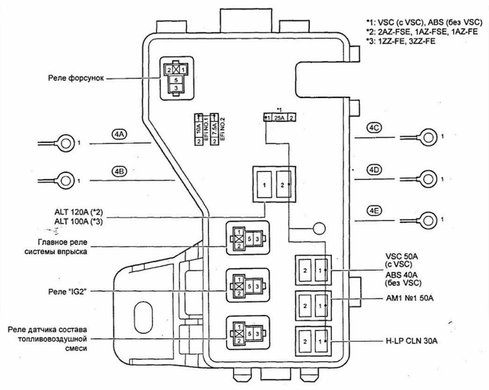
| Pozycja | Amperaż [A] | Chroniony obwód / funkcja |
|---|---|---|
| 1 | 10 | EFI NO.1: Engine management and injection |
| 2 | 7.5 | EFI NO.2: Emission control |
| 3 | 25 | VSC: ABS and VSC on models equipped with stability control |
| 3 | 25 | ABS: ABS without VSC |
| 4 | 100 | ALT: 1ZZ-FE / 3ZZ-FE main alternator power distribution |
| 4 | 120 | ALT: 1AZ-FE / 1AZ-FSE / 2AZ-FSE main alternator distribution |
| 5 | 50 | VSC: ABS and VSC when equipped |
| 5 | 40 | ABS: ABS without VSC |
| 6 | 50 | AM1 NO.1: PWR SEAT. FR DIC. FUEL OPN. ECU-B 1 and window supply |
| 7 | 30 | H-LP CLN: Headlamp washer system |
Petrol auxiliary relay positions
| Pozycja | Amperaż [A] | Chroniony obwód / funkcja |
|---|---|---|
| R1 | – | Fuel injector relay (INJ) |
| R2 | – | EFI main engine management relay (EFI) |
| R3 | – | Ignition relay (IG2) |
| R4 | – | Air-fuel ratio sensor relay (/F) |
Supplementary diesel engine fuse box
Diesel versions can have two 50 A PTC heater circuits, an 80 A glow-plug supply and a 140 A main ALT link. Older 1CD layouts and 2007 documentation may label the heater positions in a different order.
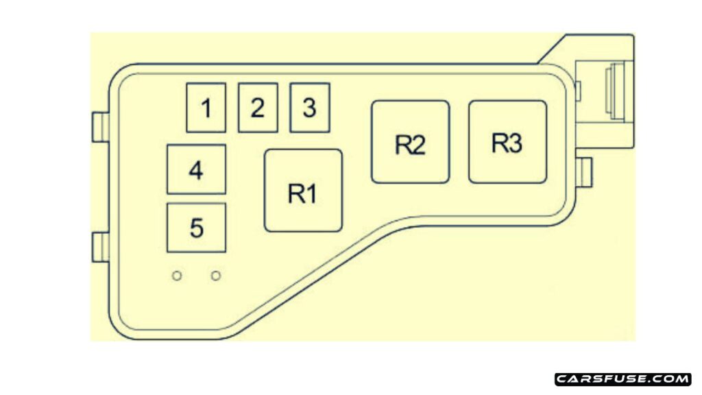
| Pozycja | Amperaż [A] | Chroniony obwód / funkcja |
|---|---|---|
| 1 | 50 | HTR1: PTC cabin heater. if installed |
| 2 | 50 | HTR2: PTC cabin heater. if installed |
| 3 | – | Unused position |
| 4 | 80 | GLOW: Diesel glow plug system |
| 5 | 140 | ALT: Main alternator and high-current distribution |
Headlamp fuses and additional relays
The lamp carrier uses separate high and dipped beam circuits for each headlamp, plus relays for the horn, fuel heater, beam switching and cooling fan.
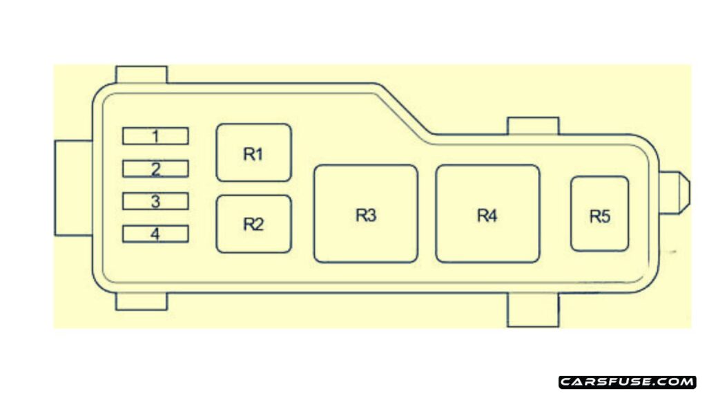
| Pozycja | Amperaż [A] | Chroniony obwód / funkcja |
|---|---|---|
| 1 | 10 | H-LP HI LH: Left high-beam headlamp |
| 2 | 10 | H-LP HI RH: Right high-beam headlamp |
| 3 | 15 | H-LP LH: Left dipped-beam headlamp |
| 4 | 15 | H-LP RH: Right dipped-beam headlamp |
Headlight and auxiliary relay assignments
| Pozycja | Amperaż [A] | Chroniony obwód / funkcja |
|---|---|---|
| R1 | – | Horn relay (HORN) |
| R2 | – | Fuel heater relay (F-HTR) |
| R3 | – | Headlamp main relay (H-LP) |
| R4 | – | Headlamp high/low beam switching relay (DIM) |
| R5 | – | Electric radiator fan relay (FAN NO.2) |
What should you check when something stops working?
Cigarette lighter dead: check CIG 15 A at position 9. For a separate power outlet inspect P/POINT 15 A at position 16. Disconnect chargers and inspect the socket for conductive debris before replacing a fuse.
Radio or navigation inoperative: RAD NO.1 (7.5 A) is on the main panel, while RAD NO.2 (15 A) is on the supplementary panel. It moves from early position 13 to position 5 on the later documented panel.
Power windows stopped: first establish whether the supplementary panel uses early window positions 2-5 or later 10-13. For imported RHD cars, consult the corresponding right-hand-drive fuse legend.
Diesel starting or heating faults: inspect only the GLOW, F-HTR and PTC circuits specified for the actual diesel engine. A repeatedly blowing fuse indicates a circuit fault; never replace it with a higher amp rating.
See the related Toyota Corolla E140/E150 article. Some fuse names are similar, but the Avensis T25 and Corolla E140/E150 have different fuse carriers and positions.