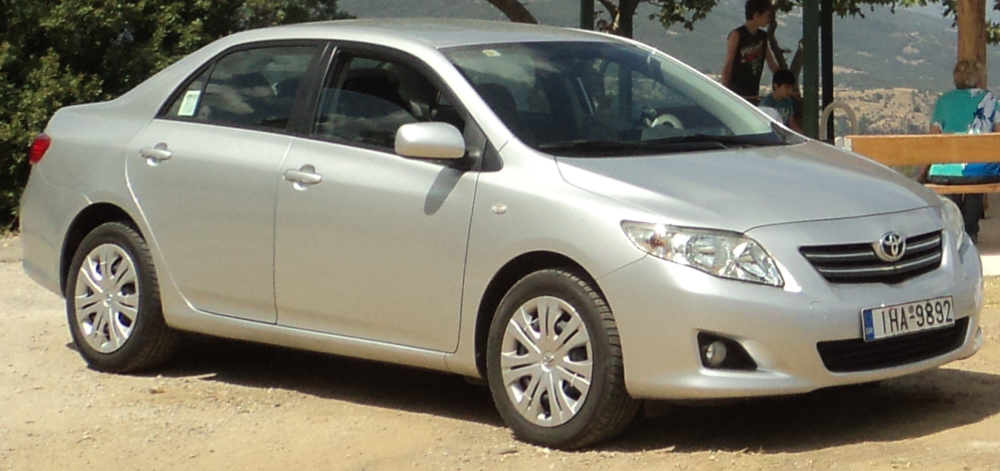
Toyota Corolla E140/E150 (2006-2013) is the tenth-generation Corolla. In European markets the E150 saloon was offered with petrol and D-4D diesel engines. Although closely related to the Toyota Auris, it must not be assumed to have the same fuse-box assignments. Fuse layout, circuit ratings and relay population differ by market, engine, production year and installed equipment.
The complete charts below include all documented spare positions, duplicate slot numbers with alternative engine-specific ratings, auxiliary PTC heater relays and cabin equipment. Before removing a fuse, compare the drawing and numbering with the physical box and the owner’s manual for the individual vehicle.
Main engine compartment fuse and relay box
Switch off the ignition, open the bonnet and find the main electrical fuse housing near the battery. Release its cover to expose protection for engine control, lighting, ABS, cooling fans, charging and the heater. The following chart includes relay sockets R1-R10 and ratings that differ between petrol, diesel and MultiMode transmission variants.
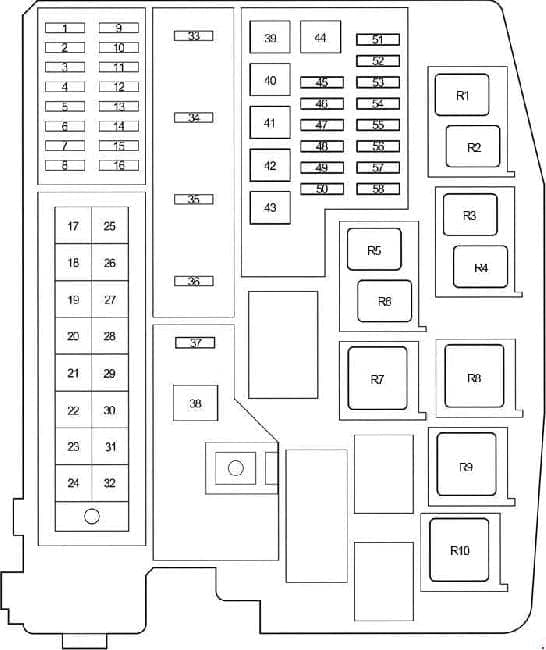
| Pozycja | Amperaż [A] | Chroniony obwód / funkcja |
|---|---|---|
| 1 | 10 | DOME: Cabin and boot lighting, remote-control receiver and smart entry where equipped |
| 2 | 15 | RAD NO.1: Audio and navigation systems |
| 3 | 10 | ECU-B: Body ECU, central locking, power windows and monitoring circuits |
| 4 | – | D.C.C: Unused in this configuration |
| 5 | 10 | ECU-B2: MultiMode manual transmission, air conditioning, smart entry / start, charging and power windows |
| 6 | – | Unused position |
| 7 | 7.5 | ECU-B3: Multipoint / sequential fuel injection |
| 8 | – | Unused position |
| 9 | 15 | IGT/INJ: Petrol fuel injection and starting system |
| 10 | 20 | STRG LOCK: Steering column lock |
| 11 | 20 | A/F: Exhaust / air-fuel control system |
| 12 | 30 | AM2: Starting system, smart entry / start and IG2 NO.2 fuse supply |
| 13 | 10 | ETCS: Electronic throttle control |
| 14 | 10 | TURN-HAZ: Turn signals and hazard lights |
| 15 | 7.5 | ALT-S: Charging system |
| 16 | 7.5 | AM2 NO.2: Main body ECU and stop-start system |
| 17 | 50 | HTR: Heater and air-conditioning blower supply |
| 18 | 50 | ABS NO.1: Antilock braking and vehicle stability control |
| 19 | 30 | CDS FAN: Cooling fan on 1AD-FTV and 2AD-FHV diesels |
| 19 | 30 | ABS NO.3: ABS and stability control on relevant petrol models |
| 20 | 40 | RDI FAN: Electric radiator cooling fan |
| 21 | 30 | H-LP CLN: Headlamp cleaning system |
| 22 | – | Unused position |
| 23 | – | Unused position |
| 24 | – | Unused position |
| 25 | – | Unused position |
| 26 | 50 | H-LP MAIN: Main headlamp supply for LH/RH low and high beam fuses |
| 27 | 50 | P/I: Power supply to EFI MAIN, EDU, HORN and IG2 fuses |
| 28 | – | Unused position |
| 29 | 30 | P-SYSTEM: Fuel injection system control |
| 30 | 80 | GLOW: Diesel glow plug system |
| 31 | 60 | EPS: Electric power steering |
| 32 | 120 | ALT (petrol): 120 A charging-system supply for associated engine and cabin fuse groups; supplies: RDI FAN, H-LP CLN, ABS NO.1, ABS NO.3, HTR, HTR SUB NO.1, HTR SUB NO.2, HTR SUB NO.3, ACC, CIG, ECU-IG NO.2, HTR-IG, WIPER, RR WIPER, WASHER, ECU-IG NO.1, SEAT HTR, AM1, DOOR, STOP, FR DOOR, POWER, RR DOOR, RL DOOR, OBD, ACC-B, RR FOG, FR FOG, SUNROOF, DEF, MIR HTR, TAIL, PANEL |
| 32 | 140 | ALT (diesel): 140 A charging-system supply for associated engine and cabin fuse groups; supplies: RDI FAN, H-LP CLN, ABS NO.1, ABS NO.3, HTR, HTR SUB NO.1, HTR SUB NO.2, HTR SUB NO.3, ACC, CIG, ECU-IG NO.2, HTR-IG, WIPER, RR WIPER, WASHER, ECU-IG NO.1, SEAT HTR, AM1, DOOR, STOP, FR DOOR, POWER, RR DOOR, RL DOOR, OBD, ACC-B, RR FOG, FR FOG, SUNROOF, DEF, MIR HTR, TAIL, PANEL, CDS FAN, ABS NO.2, STV HTR |
| 33 | 15 | IG2: Fuel injection, starting, smart entry / start and IGN / METER fuse feeds |
| 34 | 15 | HORN: Horn |
| 35 | 20 | EFI MAIN (petrol): Injection and stop-start systems; EFI NO.1 and EFI NO.2 fuses |
| 35 | 30 | EFI MAIN (diesel): Injection and stop-start systems; EFI NO.1 and EFI NO.2 fuses |
| 36 | 30 | EFI MAIN: Unused in this configuration |
| 36 | 20 | EDU: Diesel injection / engine driver electronics |
| 37 | – | Unused position |
| 38 | 40 | BBC: Stop-start system |
| 38 | 50 | AMT: MultiMode automated manual transmission |
| 39 | 30 | HTR SUB NO.3: PTC supplementary electric heater |
| 40 | – | Unused position |
| 41 | 30 | HTR SUB NO.2: PTC supplementary electric heater |
| 42 | – | Unused position |
| 43 | 30 | HTR SUB NO.1: PTC supplementary heater without 600 W option |
| 43 | 50 | HTR SUB NO.1: PTC supplementary heater with 600 W option |
| 44 | – | Unused position |
| 45 | 25 | STV HTR: Electric auxiliary heater |
| 46 | 30 | ABS NO.2: ABS and vehicle stability control |
| 47 | – | Unused position |
| 48 | – | Unused position |
| 49 | – | Unused position |
| 50 | – | Unused position |
| 51 | 10 | H-LP LH LO: Left low beam without HID |
| 51 | 15 | H-LP LH LO: Left low beam with HID |
| 52 | 10 | H-LP RH LO: Right low beam without HID |
| 52 | 15 | H-LP RH LO: Right low beam with HID |
| 53 | 10 | H-LP LH HI: Left high beam |
| 54 | 10 | H-LP RH HI: Right high beam |
| 55 | 10 | EFI NO.1: Fuel injection system |
| 56 | 10 | EFI NO.2: Fuel injection system |
| 57 | 7.5 | IG2 NO.2: Starting and smart entry / start system |
| 58 | 7.5 | WIP-S: Charging-system control circuit |
| R1 | – | R1: Unused relay position |
| R2 | – | R2: Cooling fan relay FAN NO.3 |
| R3 | – | R3: Air-fuel ratio sensor relay A/F |
| R4 | – | R4: IGT/INJ relay |
| R5 | – | R5: Cooling fan relay FAN NO.2 |
| R6 | – | R6: Cooling fan relay FAN NO.1 |
| R7 | – | R7: Dimmer relay except 1NR-FE |
| R8 | – | R8: Dimmer relay for 1NR-FE |
| R9 | – | R9: MMT automated manual transmission relay |
| R10 | – | R10: Headlamp relay H-LP |
Important: the ALT fusible link is rated at 120 A on the listed petrol variant and 140 A on the diesel version. Position 19 is separately assigned to CDS FAN or ABS NO.3 on different engines. Positions 35, 36, 38, 43, 51 and 52 likewise show alternative installations and should not be combined.
Additional relay box in the engine compartment
Some versions have another under-bonnet relay block for the supplementary electric PTC heater. Its HTR SUB stages are different from the rear-window defogger and are not fitted to every engine or market.
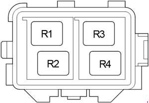
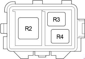
| Pozycja | Amperaż [A] | Chroniony obwód / funkcja |
|---|---|---|
| R1 | – | R1: Unused relay socket |
| R2 | – | R2: PTC heater relay HTR SUB NO.1 |
| R3 | – | R3: PTC heater relay HTR SUB NO.3 |
| R4 | – | R4: PTC heater relay HTR SUB NO.2 |
Passenger compartment fuse box
Switch off the ignition and access the lower dashboard on the driver’s side. Remove the appropriate protective panel to expose the fuse carrier. Right-hand-drive cars may require a different cover-removal step. This panel includes the central locking, brake lights, wipers, cigarette lighter, heated mirrors, air-conditioning controls and power windows.
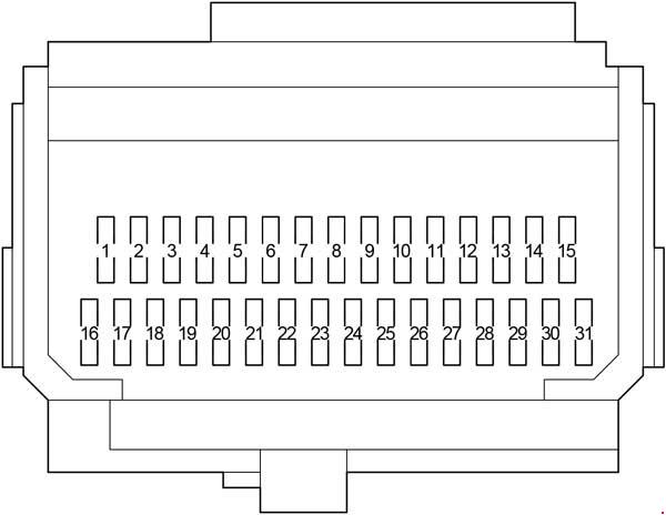
| Pozycja | Amperaż [A] | Chroniony obwód / funkcja |
|---|---|---|
| 1 | 7.5 | AM1: Starting / fuel injection; CIG and ACC fuse supply |
| 2 | 15 | FR FOG: Front fog lamps |
| 3 | – | Unused position |
| 4 | 25 | ACC-B: Power supply to CIG and ACC fuses |
| 5 | 25 | DOOR: Power door locking |
| 6 | – | Unused position |
| 7 | 10 | STOP: Stop lamps, high-mounted stop lamp, ABS and brake-signal dependent systems |
| 8 | 7.5 | OBD: On-board diagnostics |
| 9 | 10 | ECU-IG NO.2: Reverse lamps, charging, auto-dimming mirror, rear-view monitor, electric sunroof, rear-window defogger, air conditioning, turn signals, hazard lights, passenger belt reminder, stop-start and Toyota parking sensors |
| 10 | 10 | ECU-IG NO.1 without stop-start: Headlamp levelling, body ECU, EPS, cooling fans, shift interlock, rain sensor, ABS, VSC, audio, navigation, fuel injection, headlamp washers and smart entry / start |
| 11 | 15 | WASHER: Windscreen washer |
| 12 | – | Unused position |
| 13 | 25 | WIPER: Front wipers and rain sensor where equipped |
| 14 | 10 | HTR-IG: Heating and air-conditioning controls and rear-window defogger |
| 15 | 15 | SEAT HTR: Heated seats |
| 16 | 7.5 | METER: Instrument cluster and stop-start |
| 17 | 7.5 | IGN: Steering lock, SRS, MultiMode gearbox, fuel injection, smart entry / start and stop-start |
| 18 | 7.5 | RR FOG: Rear fog lamp |
| 19 | – | Unused position |
| 20 | – | Unused position |
| 21 | 10 | MIR HTR: Heated exterior mirrors |
| 22 | – | Unused position |
| 23 | 7.5 | ACC: Exterior mirrors, audio, navigation, shift interlock, body ECU, smart entry / start and stop-start |
| 24 | 15 | CIG: Factory cigarette lighter / 12 V outlet |
| 25 | 20 | SUNROOF: Electric sunroof |
| 26 | 20 | RR DOOR: Right rear door power window |
| 27 | 20 | RL DOOR: Left rear door power window |
| 28 | 20 | FR DOOR: Front door power windows |
| 29 | 10 | ECU-IG NO.1 with stop-start: Headlamp levelling, body ECU, EPS, cooling fans, shift interlock, rain sensor, ABS, VSC, audio, navigation, fuel injection, washers, smart entry / start and stop-start |
| 30 | 7.5 | PANEL: Switch, instrument-cluster and glovebox illumination, body ECU |
| 31 | 10 | TAIL: Parking lights, tail lights, plate lights, fog lights, manual headlamp levelling, fuel injection and instrument illumination |
Fuses and relays behind the interior fuse carrier
An additional block sits behind the main dashboard fuse carrier and includes POWER and DEF protection. The DEF circuit supplies rear-window demisting; MIR HTR is the mirror-heating circuit. The relay labels R1-R3 in this block must not be confused with those in the engine-bay relay box.
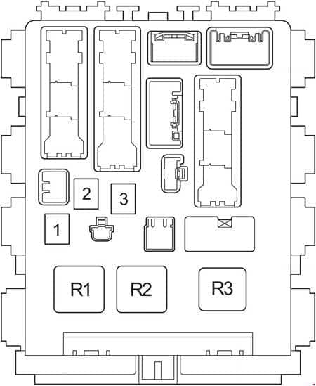
| Pozycja | Amperaż [A] | Chroniony obwód / funkcja |
|---|---|---|
| 1 | 30 | POWER: Main power-window circuit |
| 2 | 30 | DEF: Rear-window defogger and MIR HTR heated mirror supply |
| 3 | – | Unused position |
| R1 | – | R1: Ignition relay IG1 |
| R2 | – | R2: Heater relay HTR with manual A/C, or shorting link on automatic climate control |
| R3 | – | R3: Turn signal relay on LHD cars |
Additional cabin relay block – variant A
Variant A shows the starter, rear fog lamp, accessory supply and accessory cut-off relays. Which positions are occupied depends on the exact vehicle.
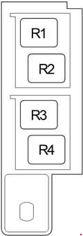
| Pozycja | Amperaż [A] | Chroniony obwód / funkcja |
|---|---|---|
| R1 | – | R1: Starter relay ST |
| R2 | – | R2: Rear fog lamp relay RR FOG |
| R3 | – | R3: Accessory relay ACC |
| R4 | – | R4: Accessory cut-off relay ACC CUT |
Additional cabin relay block – variant B
Variant B contains the front fog lamp, starter cut-off and panel illumination relay positions. R4 is shown unused; an empty original socket is not a reason to install a new relay.
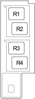
| Pozycja | Amperaż [A] | Chroniony obwód / funkcja |
|---|---|---|
| R1 | – | R1: Front fog lamp relay FR FOG |
| R2 | – | R2: Starter cut-off relay ST CUT |
| R3 | – | R3: Panel illumination relay PANEL |
| R4 | – | R4: Unused relay position |
Common fuse faults in Toyota Corolla E150
Rear-window heating not working: check DEF, position 2 (30 A), in the block behind the cabin fuse box. Heated door mirrors use MIR HTR, position 21 (10 A), in the main interior box. Also inspect the glass contacts and heating traces.
Central locking inoperative: inspect DOOR, position 5 (25 A), in the interior box. The main body ECU supply also includes ECU-B, position 3 (10 A), under the bonnet. RR DOOR, RL DOOR and FR DOOR serve the power windows, not the central door locks.
Brake lights fail: the STOP fuse is position 7 (10 A) in the cabin. If it is intact, inspect the brake pedal switch and lamp wiring.
Cigarette lighter / 12 V outlet dead: inspect CIG, position 24 (15 A), then ACC and the upstream AM1 / ACC-B feeds if several accessory functions have failed.
Blower stopped: the main under-bonnet HTR fuse (position 17, 50 A) feeds the heater and air conditioning; the dashboard has a separate HTR-IG fuse (position 14, 10 A). HTR SUB protects supplementary PTC heating stages, not the main blower.
Front wipers stopped: inspect WIPER, position 13 (25 A), in the interior panel before testing the motor and linkage.
Do the Corolla E150 and Auris have identical fuse layouts?
No. They are related vehicles but can have different fuse numbering and equipment-dependent power distribution. Match the exact model and wiring variant.
Why do ALT and EFI MAIN have several ratings?
The tables distinguish petrol and diesel powertrains as well as stop-start and other equipment variants. Use the original rating for your car; do not increase it because another version uses a larger fuse.
Does an empty relay position mean a component is missing?
Not necessarily. A shared fuse-box shell is often used across several trims and powertrains. Unpopulated relay positions can be correct from the factory.
Never bridge a fuse socket or increase the fuse size when a fuse repeatedly blows. For other English guides, visit Toyota fuse box diagrams.