
Toyota Corolla E110 (1995-2002), the eighth-generation Corolla, uses a main cabin fuse carrier, several auxiliary passenger relay boxes and a principal engine-bay fuse block. The Japanese-market E110 appeared in 1995; European-market cars commonly date from 1997 onward. Some European models registered in 1995-1997 are still the preceding E100 generation, so the chassis code is more reliable than the registration year.
Below are all 73 actual fuse, relay and alternate equipment rows from the seven technical source tables. Three empty HTML separator rows in the old Polish content have been omitted because they are not physical fuse positions. All seven original schematics remain alongside their corresponding tables, with separate descriptions for left-hand drive, right-hand drive, Daytime Running Lights (DRL), petrol engines and the 2C-E diesel.
Where are the Toyota Corolla E110 fuse boxes?
Inside the cabin: switch off the ignition, open the driver’s door and locate the lower dashboard fuse panel around the driver’s knee and footwell area in a left-hand-drive model. Gently remove its lower access cover and compare the cover legend with the numbered drawing. Some right-hand-drive variants put additional relay carriers behind the glove compartment and in the passenger footwell. Relays behind the main panel are not necessarily visible through the basic fuse opening.
Under the bonnet: open the bonnet and locate the covered engine compartment distribution box near the battery and inner wing. Release the aged plastic lid clips carefully and identify the correct main fuse/relay housing. Separate radiator fan, headlamp, ABS or air-conditioning relay holders can be positioned nearby, depending on engine and market. Main 40-100 A links must be handled with the manufacturer’s battery-disconnection procedure.
Main cabin fuse box – all 27 positions and alternatives
The cabin panel contains WIP for the front wipers, TURN for indicators, ECU-IG for accessory control, D/L for central locking and OBD for diagnostics. In the documented layout, the CIG position 19 (15 A) serves the cigarette lighter and related 12 V accessories. Position 13 ECU-B is 7.5 A on the shown LHD configuration or 5 A on RHD; position 22 DEF is 40 A on LHD or 30 A on RHD. These are alternative vehicle variants, not interchangeable fuse ratings.
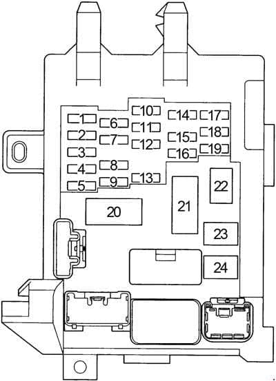
| Pozycja | Amperaż [A] | Chroniony obwód / funkcja |
|---|---|---|
| 1 | 7.5 | TURN – indicators and hazard warning lights |
| 2 | – | Unoccupied on this equipment configuration |
| 3 | 10 | GAUGE – instrument cluster, reversing lights, air conditioning, electric windows, rear defogger and power door locks |
| 4 | 20 | WIP – front windscreen wiper and washer |
| 5 | 10 | I/UP – multipoint fuel injection and electric exterior mirror controls, depending on specification |
| 5 | 10 | DEF I-UP / M-HTR – rear window defogger and multipoint fuel injection, alternative position 5 wiring |
| 6 | 10 | ECU-IG – starter system, radiator cooling fan, automatic shift lock, ABS and cruise control |
| 7 | 7.5 | IGN – petrol injection, battery charging, SRS airbags and seat belt pretensioners |
| 8 | 15 | STOP – brake/stop lamps, high-level brake lamp, ABS and automatic transmission shift lock |
| 9 | 15 | TAIL – tail and position lamps, instrument lighting, cigarette lighter associated equipment, audio, radio clock, number plate lamps, rear defogger, ECU and climate system |
| 10 | – | Unoccupied fuse position |
| 11 | – | Unoccupied fuse position |
| 12 | 7.5 | OBD – on-board diagnostics connector |
| 13 | 7.5 | ECU-B – left-hand drive (LHD): airbags, seat belt pretensioners and rear fog lamp |
| 13 | 5 | ECU-B – right-hand drive (RHD): airbags, pretensioners and rear fog lamp, lower-rated alternative |
| 14 | 5 | ST – starter and petrol engine fuel injection controls |
| 15 | 30 | D/L – central power door locking |
| 16 | 15 | FOG – front fog lamps |
| 17 | 15 | S-HTR – front seat heating |
| 18 | – | Unoccupied fuse position |
| 19 | 15 | CIG – cigarette lighter 12 V socket, audio, clock, adjustable mirrors, SRS, immobiliser and automatic selector lock |
| 20 | – | Unoccupied fuse position |
| 21 | – | NOISE FILTER – radio interference suppressor connected with DOME; not a normal blade fuse |
| 22 | 40 | DEF – LHD heated rear window main feed with auxiliary DEF I-UP/M-HTR circuit |
| 22 | 30 | DEF – RHD heated rear window main feed, 30 A factory variant |
| 23 | 30 | POWER – electric windows and factory sunroof |
| 24 | – | SHORT PIN – electrical jumper/transport bridge, not a normal replaceable fuse |
Relays behind the cabin fuse carrier
The back of the fuse panel carries a rear-window defogger relay (DEF) and a tail/position lamp relay (TAIL). Inspect the original carrier before attempting to access the rear face, which may require moving the lower trim or panel. A relay does not use a standard blade-fuse amperage.
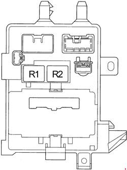
| Pozycja | Amperaż [A] | Chroniony obwód / funkcja |
|---|---|---|
| R1 | – | Rear window defogger relay (DEF), behind the cabin fuse carrier |
| R2 | – | Tail and position lamp relay (TAIL), behind the cabin fuse carrier |
Cabin auxiliary relay box 1
This auxiliary holder contains the hazard flasher, C/OPN circuit-opening fuel pump relay and P/W electric-window relay. Installed position and number may vary with equipment. The C/OPN relay supplies fuel to the engine and should not be confused with the main engine ECU relay.
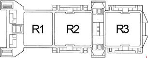
| Pozycja | Amperaż [A] | Chroniony obwód / funkcja |
|---|---|---|
| R1 | – | Hazard and direction indicator flasher relay |
| R2 | – | Circuit-opening fuel pump relay (C/OPN) |
| R3 | – | Power window relay (P/W) |
Cabin auxiliary fuse/relay box 2
A separate interior carrier supports air conditioning and heating, including A/C 15 A, HEATER 40 A and the HTR blower relay. These positions may be vacant or differently configured in cars without factory air conditioning. A blank header in the source is not a physical fuse slot.
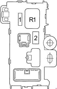
| Pozycja | Amperaż [A] | Chroniony obwód / funkcja |
|---|---|---|
| 1 | 15 | A/C – air-conditioning system and cooling fan |
| 2 | 40 | HEATER – heater/air-conditioning main power supply; related A/C fuse |
| R1 | – | HTR – heater and ventilation blower relay |
Engine compartment fuse and relay box – complete 28-row chart
The main under-bonnet unit supplies alternator, main ignition, starter, headlamps, horn, coolant fan, anti-lock braking and injection. Alternative EFI 15 A petrol and F-HTR 15 A diesel position 3 assignments are retained separately. The original listing identifies 4E-FE, 5A-FE, 4A-FE and 7A-FE petrol engines and the 2C-E diesel.
At position 2 and 8, the upper headlamp circuits carry different HEAD designations in vehicles with DRL. Position 15 may be labelled FAN or RDI depending on installation. The high-current ALT 100 A, AM1 50 A, MAIN 40 A and ABS 50 A feeds protect large groups of electrical equipment. Do not substitute a higher value when tracing a blown main fuse.
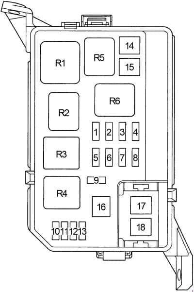
| Pozycja | Amperaż [A] | Chroniony obwód / funkcja |
|---|---|---|
| 1 | 5 | ALT-S – alternator charging signal |
| 2 | 10 | HEAD (RH) – right headlamp on cars without DRL |
| 2 | 10 | HEAD (RH-UPR) – right headlamp upper beam on cars with factory DRL |
| 3 | 15 | EFI – petrol 4A-FE, 5A-FE, 7A-FE or 4E-FE fuel injection system |
| 3 | 15 | F-HTR – 2C-E diesel fuel heating system, alternative to petrol EFI |
| 4 | 10 | HORN – horn and factory anti-theft alarm |
| 5 | 10 | HAZARD – turn indicators and emergency hazard lamps |
| 6 | 15 | AM2 – starter and IGN/ST circuit supply |
| 7 | – | Unoccupied fuse position |
| 8 | 10 | HEAD (LH) – left headlamp, without DRL |
| 8 | 10 | HEAD (LH-UPR) – left headlamp upper circuit, with DRL |
| 9 | 15 | DOME – interior, luggage, map and personal lamps, audio, clock, DRL and anti-theft system |
| 10 | – | Unoccupied position |
| 11 | – | Unoccupied position |
| 12 | – | Unoccupied position |
| 13 | – | Unoccupied position |
| 14 | 50 | AM1 – main ignition and accessories feed to CIG, TURN, GAUGE, ECU-IG and WIP |
| 15 | 30 | FAN – radiator cooling fan supply, one of two position 15 names |
| 15 | 30 | RDI – radiator cooling fan supply, alternate position 15 marking |
| 16 | 40 | MAIN – starter and main headlamp circuits, including low-beam and DRL variants |
| 17 | 100 | ALT – 100 A alternator power distribution to cooling, door locks, cabin electrics, power windows, lamps, ABS and main auxiliaries |
| 18 | 50 | ABS – anti-lock braking system high-current fuse |
| R1 | – | ENGINE MAIN – main engine control relay |
| R2 | – | EFI petrol / F-HTR diesel – engine ECU or diesel fuel heater relay, engine-specific |
| R3 | – | HEAD – headlamp relay |
| R4 | – | ST – starter motor relay |
| R5 | – | HORN – horn relay |
| R6 | – | FAN NO.1 – radiator cooling fan relay |
Engine compartment auxiliary fuse and relay box 1
This separate box can supply the radiator cooling fan, the left/right lower headlamp circuits, factory DRL and air conditioning. The original chart retains the CDS 30 A and DRL 7.5 A fuses and four local relay identities. Some cars lack factory DRL or the air-conditioning clutch, in which case the corresponding fuse or relay may be absent.
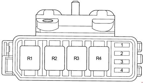
| Pozycja | Amperaż [A] | Chroniony obwód / funkcja |
|---|---|---|
| 1 | 30 | CDS – radiator cooling fan circuit |
| 2 | 10 | HEAD (LH-LWR) – left lower/dipped headlamp circuit on equipped DRL cars |
| 3 | 15 | HEAD (RH-LWR) – right lower/dipped headlamp circuit on petrol or DRL versions as fitted |
| 4 | 7.5 | DRL – daytime running light controller |
| R1 | – | DIMMER – main/dipped headlamp changeover relay |
| R2 | – | A/C FAN NO.2 – radiator or air-conditioning condenser cooling fan relay |
| R3 | – | A/C FAN NO.2 – second cooling fan relay with the same source designation |
| R4 | – | A/C MG – air-conditioning compressor magnetic clutch relay |
Engine compartment auxiliary ABS relay box 2
When factory ABS is fitted, a separate relay holder carries the ABS SOL valve relay and the ABS MTR pump motor relay. The box can be absent on cars without ABS. Neither relay should be mistaken for the high-current 50 A ABS fuse in the main engine box.

| Pozycja | Amperaż [A] | Chroniony obwód / funkcja |
|---|---|---|
| R1 | – | ABS SOL – ABS hydraulic valve relay |
| R2 | – | ABS MTR – ABS pump motor relay |
LHD/RHD, DRL, petrol and diesel equipment variations
Left versus right-hand drive: position 13 ECU-B and position 22 DEF have differing ratings in the two retained layouts. DRL: HEAD (LH-UPR), HEAD (RH-UPR), HEAD (LH-LWR), HEAD (RH-LWR) and the separate DRL fuse are equipment-dependent. Engine: EFI petrol circuits must not be assumed identical to the 2C-E diesel F-HTR heater wiring. Some years and regional configurations also use different air-conditioning and ABS relay positions.
Common Corolla E110 electrical faults
Cigarette lighter stopped working: check cabin CIG number 19 (15 A) and the socket contacts. Wipers or washer failed: inspect WIP number 4 (20 A), motor and linkage. A blown replacement can indicate a seized motor or short circuit, not a need for a larger fuse.
Rear windscreen does not defog: check DEF position 22 with the correct 40 A LHD or 30 A RHD layout, then the separate DEF relay and heating strips. Electric windows failed: inspect POWER number 23 (30 A) and the P/W relay. If one door is affected, examine its wiring and regulator.
Diagnostic tool cannot connect: verify the cabin OBD number 12 (7.5 A), then the connector power and earth terminals. Petrol no-start: IGN number 7 (7.5 A), ST number 14 (5 A), engine-bay EFI position 3 (15 A) and the C/OPN fuel pump relay can be relevant depending on the fitted engine. The 2C-E diesel has a different injection and fuel-heater arrangement.
Cooling fan not switching on: inspect FAN/RDI position 15 (30 A), CDS 30 A in the auxiliary block and its relays. ABS lamp illuminated: check the correct main ABS protection, the ABS SOL/MTR relays and retrieve diagnostic codes before replacing components.
The next generations differ electrically. See the Toyota Auris I E150 and Toyota Yaris I XP10 for their own model-specific fuse charts. Fuse numbers shared across Toyota models do not establish identical protected circuits.