
Toyota Yaris I XP10 (1999-2005) was sold with different petrol and diesel engines and market-specific wiring. This guide keeps three separate original fuse distributions: the 2000-2002 Type A/B/C chart, the revised 2003-2004 chart, and a separate Yaris/Echo/Vitz XP10 configuration. Do not combine the numbers of these layouts as if they were one vehicle.
The eight tables below preserve all 135 original fuse and relay entries, including unused positions, alternative petrol/diesel functions and high-current links. All 11 original drawings remain attached. Several early schematic files are very small, so the vehicle’s fuse cover and matching manufacturer’s manual are essential for identifying the physical position.
Where are the Toyota Yaris I fuse boxes?
Passenger compartment: switch the ignition off, open the driver door and look beneath the lower dashboard to the left of the steering wheel on a left-hand-drive Yaris. Carefully release the fuse cover and read its fuse assignment legend before removing a blade fuse with plastic pullers. On right-hand-drive versions the trim and access side may differ.
Engine compartment: open the bonnet and locate the covered electrical distribution near the battery. Release the plastic clips and compare the installed housing with the engine diagram for the correct model year. Additional relay boxes and larger alternator, ABS and heater fusible links can be separate. Do not bridge high-current links or use a fuse with a higher rating.
Toyota Yaris XP10 2000-2002 – Type A protection
The early Type A group consists of 26 numbered small fuse positions. ACC at position 13 is the cigarette lighter and radio power (15 A), while WIPER at position 16 protects the wipers (20 A). The illustrated boxes below show the engine and cabin locations for this particular documentation set.


| Pozycja | Amperaż [A] | Chroniony obwód / funkcja |
|---|---|---|
| 1 | 10 | H-LP (RH) – right-hand headlamp |
| 2 | 10 | H-LP (LH) – left-hand headlamp |
| 3 | 15 | MA2 / AM2 – starter system, SRS airbags, petrol fuel injection, immobiliser and alternator charge warning |
| 4 | – | Unused or no circuit assignment in source |
| 5 | 15 | HORN – vehicle horn |
| 6 | 15 | EFI – petrol fuel injection system |
| 7 | 15 | DOME – clock, radio, interior lighting, instrument illumination and remote locking |
| 8 | 15 | SPARE – spare 15 A fuse, not an active circuit |
| 9 | 30 | SPARE – spare 30 A fuse, not an active circuit |
| 10 | 10 | H-LP LO RH – right dipped-beam headlamp and automatic lighting |
| 11 | 10 | HEAD (LO LH) – left dipped-beam headlamp and automatic lighting |
| 12 | 10 | GAUGE – reversing lamps, charging system, air conditioning, power windows and instruments |
| 13 | 15 | ACC – cigarette lighter, clock, radio and electric mirror adjustment |
| 14 | 7.5 | A.C – air conditioning controls |
| 15 | 25 | DEF – heated rear window and exterior mirrors |
| 16 | 20 | WIPER – front and rear window wipers, washers and headlamp cleaning |
| 17 | 7.5 | ECU-IG – anti-lock braking and radiator cooling fan control |
| 18 | 10 | S-HTR – seat heating |
| 19 | 25 | D/L – central door locking |
| 20 | 7.5 | ECB-B (as labelled in source) – rear fog lamp and airbag control |
| 21 | 7.5 | OBD – onboard diagnostic connector |
| 22 | 10 | TAIL – position and tail lamps, number plate illumination, audio and headlamp levelling |
| 23 | 10 | HAZ – indicators and hazard lights |
| 24 | 10 | STOP – brake lamps, ABS, shift interlock and petrol injection control |
| 25 | 10 | H-LP HI RH – right main-beam headlamp |
| 26 | 10 | H-LP HI LH – left main-beam headlamp |
2000-2002 – Type B high-current fuses
These seven larger fuses protect heater, cooling, windows, ignition distribution and Toyota FreeTronic equipment. They must not be confused with the Type A positions of the same vehicle.


| Pozycja | Amperaż [A] | Chroniony obwód / funkcja |
|---|---|---|
| 27 | 50 | HTR SUB2 – auxiliary air conditioning / electrical heating |
| 28 | 50 | HTR SUB1 – auxiliary air conditioning / electrical heating |
| 29 | 30 | RDI – radiator cooling fans |
| 30 | 30 | CL-ALT2 – Toyota FreeTronic system |
| 31 | 50 | AM1 – main power to ACC, GAUGE, WIPER, ECU-IG, S-HTR and DEF |
| 32 | 30 | POWER – electric window motors |
| 33 | 40 | HTR – main heater and air conditioning blower power |
2000-2002 – Type C main fusible links
The separate MAIN, CL-ALT1, ALT and ABS main fuses protect the vehicle’s large power branches. ALT is listed as 100 A or 120 A depending on the documented installation, not as a freely interchangeable rating.
| Pozycja | Amperaż [A] | Chroniony obwód / funkcja |
|---|---|---|
| 34 | 60 | MAIN – main feed to EFI, DOME, HORN, starter, AM2 and headlamp fuses |
| 35 | 60 | CL-ALT1 – main link feeding CL-ALT2 |
| 36 | 100 (120) | ALT – main alternator distribution to radiator, heaters, ECU-B, lighting, door locks, OBD, power windows and brake circuits |
| 37 | 60 | ABS – anti-lock brake system main feed |
Toyota Yaris I 2003-2004 – Type A fuse positions
The later numbering differs significantly. ACC is position 11 (15 A), WIPER position 14 (20 A) and OBD position 19 (7.5 A). Position 1 can be ETCS 10 A for petrol or FUEL HTR 25 A for a diesel; position 4 can use EFI or ECDI depending on engine. These variants remain separate rows in the table.


| Pozycja | Amperaż [A] | Chroniony obwód / funkcja |
|---|---|---|
| 1 (ETCS) | 10 | ETCS – petrol engine electronic throttle / fuel injection, position 1 variant |
| 1 (FUEL HTR) | 25 | FUEL HTR – diesel fuel heater, alternate position 1 |
| 2 (HORN) | 10 | HORN – horn |
| 3 (AM2) | 30 | AM2 – starter, airbags, injection control, immobiliser and battery charge warning |
| 4 (EFI) | 15 | EFI – petrol injection, position 4 alternative |
| 4 (ECDI) | 30 | ECDI – diesel engine injection control, position 4 alternative |
| 5 (H-LP MAIN) | 20 | H-LP MAIN – headlamp main power with automatic dipped-beam switching |
| 6 (DOME) | 15 | DOME – interior lighting, clock, radio, instruments and wireless central locking |
| 7 (H-LP RH/H-LP LO RH) | 10 | H-LP RH / H-LP LO RH – right headlamp |
| 8 (H-LP LH/H-LP LO LH) | 10 | H-LP LH / H-LP LO LH – left headlamp |
| 9 (ST) | 7.5 | ST – starter and automatic transmission control |
| 10 (GAUGE) | 10 | GAUGE – reversing lamps, charge warning, climate controls, windows, instruments, central locking and shift interlock |
| 11 (ACC) | 15 | ACC – cigarette lighter, clock, radio and exterior mirror motors |
| 12 (A.C) | 7.5 | A.C – air conditioning |
| 13 (DEF) | 25 | DEF – heated rear window and heated exterior mirrors |
| 14 (WIPER) | 20 | WIPER – front and rear window wipers and washers |
| 15 (ECU-IG) | 7.5 | ECU-IG – anti-lock brakes, cooling fan and airbags |
| 16 (P S-HTR) | 10 | P S-HTR – front passenger seat heater |
| 17 (D/L) | 25 | D/L – central door locking |
| 18 (ECU-B) | 7.5 | ECU-B – rear fog lamp |
| 19 (OBD) | 7.5 | OBD – onboard diagnostics |
| 20 (D S-HTR) | 10 | D S-HTR – driver seat heater |
| 21 (TAIL) | 7.5 | TAIL – position lamps, rear lamps, number plate lighting, audio and headlamp adjustment |
| 22 (FOG) | 15 | FOG – front fog lamps |
| 23 (HAZ) | 10 | HAZ – indicators and hazard lamps |
| 24 (STOP) | 10 | STOP – brake lamps, ABS, shift interlock and engine injection |
| 25 (ECD2) | 15 | ECD2 – diesel engine management |
| 26 (IG2) | 15 | IG2 – ignition system, fuel injection and automatic gearbox |
| 27 (I/UP) | 10 | I/UP – engine management controller |
| 28 (EFI NO.2) | 10 | EFI NO.2 – engine management |
| 29 (H-LP HI RH) | 10 | H-LP HI RH – right high-beam headlamp |
| 30 (H-LP HI LH) | 10 | H-LP HI LH – left high-beam headlamp |
2003-2004 – Type B main fuses
This later engine and high-current block includes alternator power, ABS, electric steering, cooling, windows, heater and automated manual transmission. Do not apply the earlier 2000-2002 fuse numbers to this carrier.


| Pozycja | Amperaż [A] | Chroniony obwód / funkcja |
|---|---|---|
| 31 (ABS) | 60 | ABS – anti-lock brake system |
| 32 (ALT) | 120 | ALT – main charging and power distribution to cabin and engine circuits |
| 33 (HTR SUB2) | 30 | HTR SUB2 – auxiliary cabin heating |
| 34 (RDI) | 30 | RDI – electric radiator cooling fan |
| 35 (EMPS) | 50 | EMPS – electric power steering |
| 36 (HTR SUB1) | 30 | HTR SUB1 – supplementary cabin heating |
| 37 (AMT) | 50 | AMT – automated manual gearbox |
| 38 (AM1) | 50 | AM1 – main ignition accessory circuit supply |
| 39 (POWER) | 30 | POWER – electric windows |
| 40 (HTR) | 40 | HTR – heater and air conditioning blower power |
Yaris / Echo / Vitz XP10 – alternative engine fuse and relay box
These are distinct model-market arrangements, not additional positions for the preceding European chart. The engine box has fuse positions 1-17 and relays R1-R9. Petrol EFI, headlamps, starter, cooling and PTC heater are individually protected. A no-fuse or spare location is not a cue to insert a replacement.
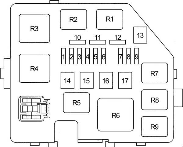
| Pozycja | Amperaż [A] | Chroniony obwód / funkcja |
|---|---|---|
| 1 (DOME) | 15 | DOME – clocks, combination instruments, double locking, headlights, interior lighting, audio, multimedia and wireless central locking |
| 2 (EFI) | 15 | EFI – petrol injection control, automatic transmission and immobiliser |
| 3 (HORN) | 15 | HORN – horn |
| 4 (AM2) | 15 | AM2 – charging, instruments, automatic transmission, injection, SRS airbags and starter |
| 5 (ST) | 30 | ST – starter motor and ignition |
| 6 (-) | – | Unused fuse position |
| 7 (H−LP LH or H−LP LO LH) | 10 | H-LP LH / H-LP LO LH – left headlamp and headlamp levelling with daytime running lights |
| 8 (H−LP RH or H−LP LO RH) | 10 | H-LP RH / H-LP LO RH – right headlamp and levelling with daytime running lights |
| 9 (P/POINT) | 15 | P/POINT – auxiliary 12 V power outlet |
| 10 (-) | – | Spare fuse position |
| 11 (-) | – | Spare fuse position |
| 12 (-) | – | Spare fuse position |
| 13 (-) | – | Unassigned position |
| 14 (-) | – | Unused fuse position |
| 15 (RDI) | 30 | RDI – radiator and air conditioning condenser cooling fan |
| 16 (HTR SUB1) | 50 | HTR SUB1 – PTC electric heater |
| 17 (-) | – | Unused position |
| R1 | – | R1 – radiator fan relay |
| R2 | – | R2 – radiator fan relay |
| R3 | – | R3 – starter motor relay |
| R4 | – | R4 – unoccupied relay socket |
| R5 | – | R5 – accessory power outlet relay |
| R6 | – | R6 – electric PTC heating relay |
| R7 | – | R7 – electronic fuel injection relay |
| R8 | – | R8 – air conditioning compressor clutch relay |
| R9 | – | R9 – horn relay |
Yaris / Echo / Vitz – separate headlamp fuse and relay box
The smaller engine carrier contains left/right high-beam fuses and three relay positions. Its R numbering is local to this specific small carrier, not a universal number across all XP10 relay boxes.
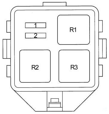
| Pozycja | Amperaż [A] | Chroniony obwód / funkcja |
|---|---|---|
| 1 (H-LP HI RH) | 10 | H-LP HI RH – right high-beam headlamp, daytime running light system |
| 2 (H-LP HI LH) | 10 | H-LP HI LH – left high-beam headlamp and instrument light, daytime running light system |
| R1 | – | R1 – main headlamp relay |
| R2 | – | R2 – headlamp dimmer relay |
| R3 | – | R3 – unoccupied relay socket |
Yaris / Echo / Vitz – alternative interior fuse panel
This market configuration numbers the cigarette lighter as ACC position 9 (15 A), the front and rear wiper supply as WIPER position 6 (20 A) and the onboard diagnostic system as OBD position 11 (7.5 A). These differ from the earlier 2000-2002 and the later 2003-2004 tables above.
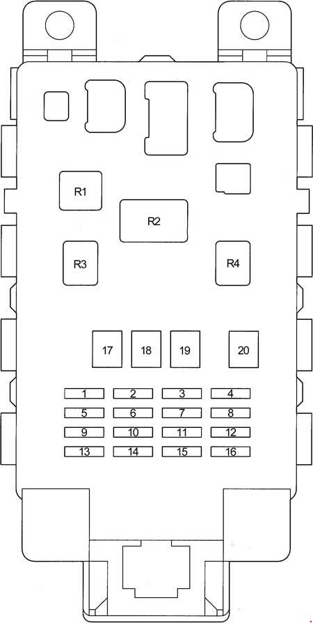
| Pozycja | Amperaż [A] | Chroniony obwód / funkcja |
|---|---|---|
| 1 (GAUGE) | 10 | GAUGE – ABS, climate, rear lamps, charging, instrument cluster, locking, automatic transmission, injection, electric windows, shift lock and indicators |
| 2 (DEF RLY) | 10 | DEF RLY – heated rear window and heated exterior mirror relay circuit |
| 2 (DEF) | 20 | DEF – heated rear window and exterior mirror circuit |
| 3 (D/L) | 25 | D/L – central locking and double locking |
| 4 (TAIL) | 7.5 | TAIL – parking lamps, headlamps, fog lamps, levelling and switch illumination |
| 5 (-) | – | Unused position |
| 6 (WIPER) | 20 | WIPER – front and rear wipers and washers, door locking controls |
| 7 (ECU−B) | 7.5 | ECU-B – headlamp and rear fog lamp functions |
| 8 (FOG) | 15 | FOG – front fog lamps |
| 9 (ACC) | 15 | ACC – cigarette lighter, 12 V outlet, radio, clock, instruments, multifunction display and electric mirrors |
| 10 (ECU−IG) | 7.5 | ECU-IG – ABS, cabin lights, multimedia, electric PTC heater, cooling fan and SRS |
| 11 (OBD) | 7.5 | OBD – diagnostic connector |
| 12 (HAZ) | 10 | HAZ – indicators and hazard lamps |
| 13 (A.C) | 7.5 | A.C – air conditioning and heating |
| 14 (S-HTR) | 10 | S-HTR – seat heating |
| 15 (-) | – | Unused position |
| 16 (STOP) | 10 | STOP – brake lights, automatic transmission, injection and shift lock |
| 17 (AM1) | 50 | AM1 – main ignition accessories supply to ACC, GAUGE, DEF, seat heaters, WIPER and ECU-IG |
| 18 (POWER) | 30 | POWER – electric windows and optional sunroof |
| 19 (HTR) | 40 | HTR – heater and air conditioning |
| 20 (DEF) | 30 | DEF – heated rear window and mirror power |
| R1 | – | R1 – heater / air conditioning relay |
| R2 | – | R2 – headlamp relay |
| R3 | – | R3 – power relay |
| R4 | – | R4 – circuit opening relay for fuel system |
Common Yaris XP10 electrical problems
Cigarette lighter not working: check the installed wiring version first. The 2000-2002 chart uses ACC 13 (15 A); the 2003-2004 chart ACC 11 (15 A); the separate Echo/Vitz layout ACC 9 (15 A). Inspect the socket for conductive debris before fitting the same amperage.
Wipers stopped: check WIPER 16 (20 A), WIPER 14 (20 A) or WIPER 6 (20 A) depending on the matching chart. A good fuse does not exclude motor, linkage or switch damage.
Heated rear window or power windows failed: inspect the relevant DEF and POWER links for the specific version, plus heater wiring in the rear hatch. Diesel starting or fuel-heating problem: verify the diesel FUEL HTR and ECDI supplies against the actual engine, not the petrol ETCS / EFI alternatives.
ABS or steering warning: check only the ABS and EMPS high-current ratings applicable to the vehicle, then retrieve fault codes. Do not replace a 60 A or 120 A main link without confirming the cause of an overload.
The next generation uses different numbering: Toyota Yaris II XP90 (2005-2012). The related Toyota Auris I E150 also has its own fuse box arrangement.