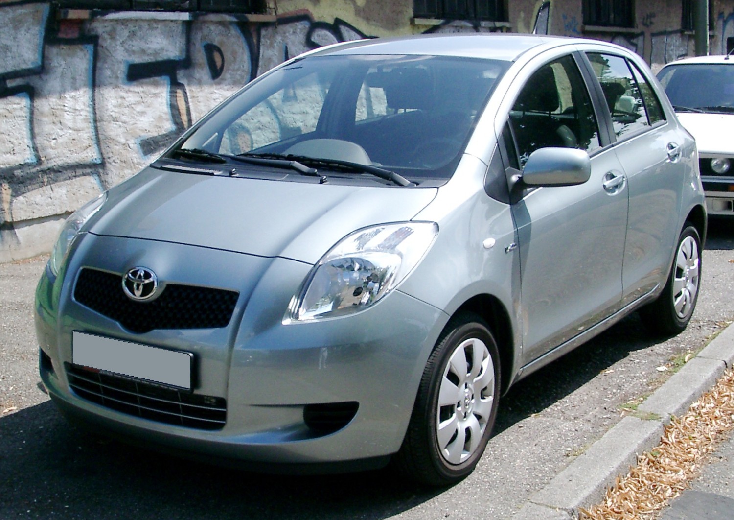
Toyota Yaris II (XP90, 2005-2012) is the second-generation European Yaris with petrol and diesel engine variants. Its electrical system is divided into a main passenger-compartment fuse carrier, additional cabin fuses and relays, a main engine-bay junction box and supplementary engine relay blocks. Fuse allocations vary with engine, MultiMode MMT transmission, Stop & Start, daytime running lights and optional PTC cabin heating.
All 108 actual fuse and relay entries and alternatives from the original Polish article are retained in the seven tables. Four rows used only as relay-section headings have been omitted from the data tables. Alternative engine codes and heater wattages remain explicit; the fitted fuse lid and the vehicle’s original market-specific fuse card take precedence when selecting an amperage.
Toyota Yaris II XP90 – where are the fuse boxes?
Inside the cabin: switch off the ignition and all accessories, move the front seat rearwards and locate the lower dashboard service cover on the driver’s side of a left-hand-drive car. Release the cover to reach the main panel. The separate PWR/DEF junction and accessory relay box are mounted around the same lower dashboard area; do not disconnect SRS or steering-column wiring when removing trim.
Under the bonnet: the main fuse and relay box sits near the battery. Open the bonnet and release the fuse-box lid clips with the ignition off. Compare its diagram with the relevant 1KR-FE, 1NZ-FE, 2NZ-FE, 2SZ-FE, 2ZR-FE petrol or 1ND-TV diesel equipment. Supplementary relays can be mounted in adjacent housings; not all positions appear in every car.
Main passenger compartment fuse box – 33 documented entries
Some labels use the same physical number for alternative equipment: slot 1 can carry TAIL or PANEL2 circuits on different cards, while WIP at position 19 is shown with both 20 A and 25 A versions. The front 12 V cigarette lighter uses CIG, position 8, 15 A; the diagnostic socket is OBD2, position 24, 7.5 A.

| Pozycja | Amperaż [A] | Chroniony obwód / funkcja |
|---|---|---|
| 1 | 10 | TAIL – side marker, parking, rear and licence-plate lamps and petrol injection |
| 1 | 7.5 | PANEL2 – immobiliser, smart entry, front/rear fog lamps, MMT transmission, steering lock, lighting and door locks, variant of slot 1 |
| 2 | 7.5 | PANEL1 – instrument and switch illumination, gauges |
| 3 | 7.5 | A/C – air conditioning and heated rear window |
| 4 | 20 | D DOOR – driver’s electric window |
| 5 | 20 | RL DOOR – left rear passenger electric window |
| 6 | 20 | RR DOOR – right rear passenger electric window |
| 7 | – | – – Unoccupied position |
| 8 | 15 | CIG – 12 V accessory / cigarette lighter socket |
| 9 | 7.5 | ACC – door locking, outside mirrors and audio system |
| 10 | – | – – Unoccupied position |
| 11 | 10 | ID/UP /MIR HTR – ID/UP / MIR HTR – fuel injection and heated mirrors, equipment dependent |
| 12 | – | – – Unoccupied position |
| 13 | – | – – Unoccupied position |
| 14 | 7.5 | RR FOG – rear fog lamp |
| 15 | 7.5 | IGN – petrol injection, immobiliser, SRS airbags and passenger occupancy classification |
| 16 | 7.5 | MET – instrument cluster, gauges and meters |
| 17 | 15 | P S-HTR – front passenger heated seat |
| 18 | 15 | D S-HTR – driver heated seat |
| 19 | 20 | WIP – front wiper motor, 20 A on one factory arrangement |
| 19 | 25 | WIP – front wiper motor, 25 A on alternate equipment card |
| 20 | 15 | RR WIP – rear windscreen wiper |
| 21 | 15 | WSH – windscreen washer motor |
| 22 | 10 | ECU-IG – daytime running lights, ABS, electric steering, windows, door locking, immobiliser and cooling fan |
| 23 | 10 | GAUGE – charging, indicators, hazard lamps, dash lighting, shift lock, rear defogger, A/C and automatic transmission |
| 24 | 7.5 | OBD2 – diagnostic socket |
| 25 | 10 | STOP – brake lamps, petrol injection, shift interlock and ABS |
| 26 | – | – – Unoccupied position |
| 27 | 25 | D/L – central door locking |
| 28 | 15 | FR FOG – front fog lamps |
| 29 | – | – – Unoccupied position |
| 30 | 10 | TAIL – side marker, tail and licence plate lamps, petrol injection |
| 31 | 25 | AM1 – petrol engine injection / power supply |
Auxiliary cabin fuse holder and relays
This section retains the PWR (30 A) electric window feed, DEF (30 A) rear window heating feed, an unoccupied position and the relevant ignition, heating and lighting relays. The relay positions have no applicable blade-fuse amperage.
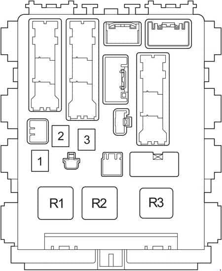
| Pozycja | Amperaż [A] | Chroniony obwód / funkcja |
|---|---|---|
| 1 | 30 | PWR – electric windows |
| 2 | 30 | DEF – rear window defogger |
| 3 | – | – – Unoccupied position |
| R1 | – | Ignition relay IG1 |
| R2 | – | Heating and ventilation relay HTR |
| R3 | – | Lighting relay |
Additional cabin fuse carrier variants
The small supplementary panel has two documented physical configurations in the source drawing. The original lists ACC2, AM2 NO.2 and WIP-S for both variants. T1 and T2 below identify the layout type, not three fuses in the same numbered cavity. Do not fit a fuse without the installed car’s own diagram.

| Pozycja | Amperaż [A] | Chroniony obwód / funkcja |
|---|---|---|
| T1 | 7.5 | ACC2 – transmission shift interlock, auxiliary layout type 1 |
| T1 | 7.5 | AM2 NO.2 – charging, door locking, immobiliser, smart key, starting, steering lock and interior lights, layout type 1 |
| T1 | 7.5 | WIP-S – charging system, layout type 1 |
| T2 | 7.5 | ACC2 – transmission shift interlock, auxiliary layout type 2 |
| T2 | 7.5 | AM2 NO.2 – charging, door locking, immobiliser, smart key, starting, steering lock and interior lights, layout type 2 |
| T2 | 7.5 | WIP-S – charging system, layout type 2 |
Main engine compartment fuse box – petrol, diesel and equipment variants
Fuel injection, cooling, charging, electric steering, ABS and the headlights are covered here. Early Yaris XP90 petrol and diesel vehicles use different EFI/ECD and horn positions at the start of the block. The 435 W versus 600 W PTC electric heater, MultiMode transmission and Stop & Start circuits also change occupied positions and ratings.
Specific examples include EPS (50 A), ABS1/VSC1 (50 A), RDI cooling fan (30 A), AMT (50 A) for MultiMode or BBC (40 A) for Stop & Start at position 21. The extra ST, cooling fan and heater relays follow the fuse list with distinct R codes.

| Pozycja | Amperaż [A] | Chroniony obwód / funkcja |
|---|---|---|
| 1 | – | – – Unoccupied engine fuse position 1 |
| 2 | 15 | AM2 – starting and petrol injection |
| 3 | 20 | EFI – petrol engine injection, position 3 variant |
| 3 | 10 | HORN – horn, position 3 on applicable petrol engine codes |
| 3 | 30 | ECD – diesel injection, position 3 on applicable diesels |
| 4 | 10 | HORN – horn, position 4 on 1KR-FE and diesel 1ND-TV |
| 4 | 20 | EFI – petrol injection, position 4 alternate |
| 4 | 30 | ECD – diesel injection, position 4 on TMMF vehicles built from November 2008 |
| 5 | 30 | – – SPARE – 30 A replacement fuse, not an active circuit |
| 6 | 10 | – – SPARE – 10 A replacement fuse |
| 7 | 15 | – – SPARE – 15 A replacement fuse |
| 8 | – | – – Unoccupied position |
| 9 | – | – – Unoccupied position |
| 10 | – | – – Unoccupied position |
| 11 | 20 | FR DEF – front windscreen de-icer on equipped vehicles; circuit not specified in source |
| 12 | 30 | ABS2/VSC2 – ABS and vehicle stability control |
| 13 | 30 | H-LP MAIN – main headlight fuse, daytime running lights variant |
| 14 | 30 | ST – starter motor system |
| 15 | 20 | S-LOCK – steering lock |
| 16 | 15 | DOME – interior lamps, anti-theft system, audio and remote door locks |
| 17 | 7.5 | ECU-B – immobiliser, daytime running lights, passenger classification, windows, locks, alarm and gauges |
| 18 | 7.5 | ALT-S – charging control |
| 19 | 10 | ETCS – electronic throttle control and injection |
| 20 | 10 | HAZ – direction indicators and hazard flashers |
| 21 | 50 | AMT – MultiMode automated manual transmission |
| 21 | 40 | BBC – Start & Stop, alternate position 21 |
| 22 | 10 | H-LP RH /H-LP LO RH – H-LP RH / H-LP LO RH – right headlamp |
| 23 | 10 | H-LP LH /H-LP LO LH – H-LP LH / H-LP LO LH – left headlamp |
| 24 | 10 | EFI2 – petrol injection, position 24 variant |
| 24 | 10 | ECD2 – diesel injection, alternate position 24 |
| 25 | 7.5 | ECD3 – diesel engine injection |
| 26 | 40 | HTR SUB2 – 435 W PTC electric heater, position 26 |
| 26 | 50 | HTR SUB1 – 600 W PTC electric heater, position 26 alternative |
| 27 | 50 | EPS – electric power steering |
| 28 | 50 | ABS1/VSC1 – ABS and stability control main supply |
| 29 | 40 | HTR – cabin heating and air conditioning |
| 30 | 30 | RDI – electric radiator cooling fan |
| 31 | 30 | HTR SUB1 – 435 W PTC heater circuit, position 31 |
| 31 | 30 | HTR SUB2 – 600 W PTC heater circuit, position 31 alternative |
| 32 | 30 | H-LP CLN /PWR HTR – H-LP CLN / PWR HTR – headlamp washer or supplementary electric heater |
| 32 | 30 | HTR SUB3 – 600 W PTC heater, position 32 alternative |
| R1 | – | Starter relay ST |
| R2 | – | Engine cooling fan relay FAN NO.2 |
| R3 | – | Electric PTC heater relay HTR SUB1 |
Engine relay panel with daytime running lights
The relay block retains both unoccupied fuse slots and 10 A high-beam feeds, then the dimmer, stability control and three PTC heater relays. Its factory options must match the installed DRL and stability-control equipment.
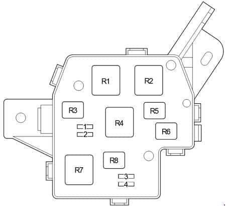
| Pozycja | Amperaż [A] | Chroniony obwód / funkcja |
|---|---|---|
| 1 | – | – – Unoccupied relay carrier fuse slot |
| 2 | – | – – Unoccupied relay carrier fuse slot |
| 3 | 10 | H-LP HI RH – right main beam |
| 4 | 10 | H-LP HI LH – left main beam |
| R1 | – | Headlamp dimmer relay DIM |
| R2 | – | VSC1 / ABS1 / MMT transmission relay |
| R3 | – | Unoccupied relay position |
| R4 | – | Main headlamp relay H-LP |
| R5 | – | PTC heater relay HTR SUB3 |
| R6 | – | PTC heater relay HTR SUB2 |
| R7 | – | PTC heater relay HTR SUB1 |
| R8 | – | VSC2 / ABS2 relay |
Supplementary engine fuse and relay box – type 1
Two sockets are unoccupied in this configuration. The VSC1 and VSC2 / front windscreen defogger relays are separately identified; these are not amperage-rated blade fuses.
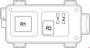
| Pozycja | Amperaż [A] | Chroniony obwód / funkcja |
|---|---|---|
| 1 | – | – – Unoccupied relay/fuse position |
| 2 | – | – – Unoccupied relay/fuse position |
| R1 | – | VSC1 stability control relay |
| R2 | – | VSC2 / front de-icer relay FR DEF |
Supplementary engine relay box – type 2
This variant includes three relay functions for auxiliary PTC heating and, depending on equipment, headlights and MultiMode MMT control.
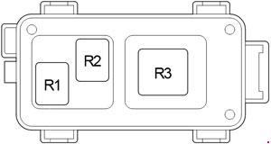
| Pozycja | Amperaż [A] | Chroniony obwód / funkcja |
|---|---|---|
| R1 | – | Electric PTC heater relay HTR SUB3 |
| R2 | – | Electric PTC heater relay HTR SUB2 |
| R3 | – | Headlamp, MultiMode MMT or PTC heater relay H-LP / AMT / HTR SUB1 |
Practical electrical troubleshooting
Cigarette lighter and 12 V outlet not working: inspect interior CIG position 8 (15 A). Unplug chargers and inspect the socket for small metal debris before installing the same rated fuse. Front wipers stopped: interior WIP position 19; check whether the actual car uses 20 A or 25 A. The rear wiper has RR WIP position 20 (15 A).
Power windows or rear defogger failed: the auxiliary interior holder carries PWR (30 A) and DEF (30 A). If only one door fails, also inspect its window motor wiring. Engine does not start: use the correct petrol EFI or diesel ECD fuse and AM2 starter supply, not a mismatched fuse card.
ABS warning: verify the ABS1/VSC1 and ABS2/VSC2 supplies before diagnostics. Weak cabin heating: only vehicles with the specified PTC heater use HTR SUB1/2/3 circuits, and the 435 W and 600 W versions have different assignments.
Other related English diagrams are available for the Toyota Auris I and Toyota Corolla E140/E150. Similar Toyota fuse names do not establish identical numbered positions.