
The BYD Seal U EV (2024) is the fully electric version of the Seal U SUV. These fuse assignments are based on the European September 2024 BYD Seal U EV owner’s manual. It describes two low-voltage fuse boxes: dashboard positions 01-31 and front-compartment positions F1-F53.
These diagrams apply to the battery-electric Seal U EV, not the Seal U DM-i plug-in hybrid, which has a different electrical architecture. The source covers SA3(E-L) and SA3(E-H) variants in a common fuse chart. Never transfer entries from the DM-i model or a different BYD vehicle without confirming the correct lid label.
Where are the BYD Seal U EV fuse boxes?
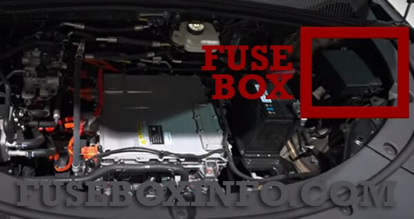
The dashboard PDB is behind the lower dashboard trim on the driver’s side. The under-hood fuse box is inside the front compartment beneath a removable protective cover. Regular and high-current fuses are included in the front distribution system, with some relay positions visible on the factory drawing.
| Fuse box | Location | Positions |
|---|---|---|
| Dashboard PDB | Lower dashboard, driver’s side | 01-31 |
| Under-hood fuse box | Under the front bonnet | F1-F53 and relay locations shown on the diagram |

For left-hand-drive cars, access to the dashboard panel is from the driver’s side. Right-hand-drive panel access may differ, so verify your own vehicle before removing trim.
BYD Seal U EV 2024 dashboard fuse box 01-31
The interior panel protects body controllers, the multimedia unit, wireless phone charging, OBD diagnostics, electrically adjustable seats, eCall, rear USB and trailer electrics. The factory uses two-digit numbers 01-31, not the F designations used under the bonnet.
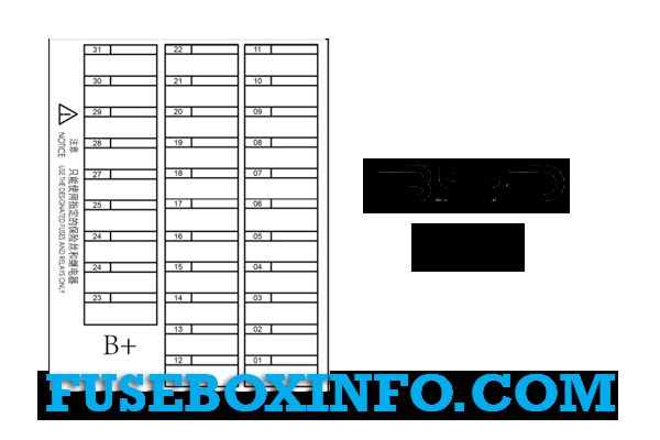
| Position | Amperage [A] | Protected circuit / function |
|---|---|---|
| 01 | 30 A | Rear body control module |
| 02 | 30 A | Universal controller |
| 03 | 30 A | Universal controller |
| 04 | 10 A | Diagnostic connector |
| 05 | 10 A | Wireless phone charger |
| 06 | 5 A | High-frequency receiver module |
| 07 | 5 A | Gear selection panel |
| 08 | 20 A | Multimedia system |
| 09 | 20 A | External audio amplifier |
| 10 | 7.5 A | Advanced driver assistance systems (ADAS) |
| 11 | 10 A | Combination switch |
| 12 | – | Unused position |
| 13 | – | Unused position |
| 14 | 10 A | Alcohol interlock interface, if fitted |
| 15 | 10 A | Left rear lamp assembly |
| 16 | 10 A | Right rear lamp assembly |
| 17 | 7.5 A | Emergency call system (eCall) |
| 18 | 5 A | Brake lamp switch |
| 19 | 30 A | Rear body control module |
| 20 | 30 A | Rear body control module |
| 21 | 30 A | Left front power seat |
| 22 | 30 A | Right front power seat |
| 23 | 20 A | Towbar/trailer electrical supply |
| 24 | 15 A | Rear USB ports |
| 25 | – | Unused position |
| 26 | – | Unused position |
| 27 | – | Unused position |
| 28 | – | Unused position |
| 29 | – | Unused position |
| 30 | – | Unused position |
| 31 | – | Unused position |
Important source detail: BYD’s September 2024 manual lists position 02 as a 30 A Universal Controller fuse, and position 03 likewise as 30 A. Some third-party charts leave 02 blank. This article follows the manufacturer chart rather than copying those omissions.
BYD Seal U EV 2024 under-bonnet fuse panel F1-F53
The front fuse box covers low-voltage supplies for the high-voltage integrated controller, thermal management, coolant pumps, battery controller, ESC, EPS, lighting, wipers, HVAC and accessory power. F49-F53 include main high-current distribution circuits, which require appropriate service procedures.
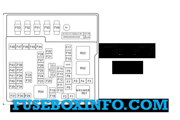
| Position | Amperage [A] | Protected circuit / function |
|---|---|---|
| F1 | 30 A | Constant power supply |
| F2 | 60 A | Dashboard PDB power distribution supply |
| F3 | – | Unused position |
| F4 | 15 A | Integrated high-voltage controller, auxiliary power supply |
| F5 | 15 A | Integrated high-voltage controller, auxiliary power supply |
| F6 | – | Unused position |
| F7 | – | Unused position |
| F8 | – | Unused position |
| F9 | 10 A | Integrated thermal management module |
| F10 | 15 A | Left headlamp assembly |
| F11 | 15 A | Right headlamp assembly |
| F12 | – | Unused position |
| F13 | – | Unused position |
| F14 | – | Unused position |
| F15 | – | Unused position |
| F16 | 40 A | Constant power supply |
| F17 | – | Unused position |
| F18 | – | Unused position |
| F19 | – | Unused position |
| F20 | – | Unused position |
| F21 | 30 A | Front windscreen wipers |
| F22 | 30 A | Heated rear window |
| F23 | 20 A | High-pressure cooling system oil pump |
| F24 | 7.5 A | Electric coolant pump |
| F25 | 7.5 A | Compressor |
| F26 | 7.5 A | USB circuit |
| F27 | 15 A | Auxiliary power / accessory supply |
| F28 | – | Unused position |
| F29 | – | Unused position |
| F30 | 60 A | Electronic Stability Control (ESC) |
| F31 | – | Unused position |
| F32 | 30 A | Towbar/trailer electrical supply |
| F33 | 5 A | Battery manager control module |
| F34 | 15 A | Heated steering wheel |
| F35 | 5 A | Rear body control module |
| F36 | 5 A | Gear selection panel |
| F37 | 7.5 A | ETC – manufacturer’s original designation |
| F38 | 10 A | Supplemental Restraint System (SRS) airbag controller |
| F39 | 5 A | Advanced driver assistance systems (ADAS) |
| F40 | 5 A | Instrument cluster |
| F41 | 5 A | Electric Power Steering (EPS) |
| F42 | 5 A | Electronic Stability Control (ESC) |
| F43 | – | Unused position |
| F44 | 60 A | Electronic Stability Control (ESC) |
| F45 | 40 A | Cabin HVAC blower |
| F46 | – | Unused position |
| F47 | – | Unused position |
| F48 | 10 A | Rear window wiper |
| F49 | 200 A | 12 V low-voltage battery main supply |
| F50 | 70 A | Column-mounted Electric Power Steering (C-EPS) |
| F51 | 100 A | Left body control module |
| F52 | 100 A | Right body control module |
| F53 | 60 A | Variable-speed electric cooling fan |
The factory drawing shows relay positions, including R01-R04. However, the owner’s guide does not identify every relay function. Unverified relay assignments have therefore not been added.
Check F26 and F39 carefully: the original September 2024 chart lists F26 (7.5 A) for USB and F39 (5 A) for ADAS. Some unofficial references give different values or incorrectly mark F26 as unoccupied.
BYD Seal U EV accessory power, USB and commonly used fuses
The manufacturer calls F27 (15 A) Auxiliary power. It is an accessory-supply circuit, but the generic fuse table does not explicitly identify it as the cigarette lighter socket. Do not label it as a specific physical socket without inspecting the installed vehicle equipment.
USB supply is listed at F26 (7.5 A) in the front box, with dashboard 24 (15 A) for rear USB. The wireless phone charger is supplied by dashboard 05 (10 A). Other common circuits are shown in the table below.
| Circuit / accessory | Fuse | Amperage [A] | Box |
|---|---|---|---|
| Auxiliary/accessory power supply | F27 | 15 A | Front compartment |
| USB circuit | F26 | 7.5 A | Front compartment |
| Rear USB ports | 24 | 15 A | Dashboard |
| Wireless phone charger | 05 | 10 A | Dashboard |
| Multimedia system | 08 | 20 A | Dashboard |
| External audio amplifier | 09 | 20 A | Dashboard |
| Diagnostic connector | 04 | 10 A | Dashboard |
| Front windscreen wipers | F21 | 30 A | Front compartment |
| Rear window wiper | F48 | 10 A | Front compartment |
| Rear window defogger | F22 | 30 A | Front compartment |
| Cabin HVAC blower | F45 | 40 A | Front compartment |
| Heated steering wheel | F34 | 15 A | Front compartment |
| Left headlamp | F10 | 15 A | Front compartment |
| Right headlamp | F11 | 15 A | Front compartment |
| Driver assistance systems (ADAS) | F39 and 10 | 5 A and 7.5 A | Front compartment / dashboard |
Both F4 and F5 are 15 A low-voltage supply circuits for the integrated high-voltage control unit. Their presence in the normal fuse listing does not make the traction battery or orange high-voltage cables safe to access. Never open protected high-voltage equipment.
Seal U EV, Seal U DM-i and BYD ATTO 3 differences
The Seal U DM-i is a plug-in hybrid with different electrical equipment and fuse box arrangements. The BYD ATTO 3 is also electric, but its 01-31 and F1-F53 allocations are not equivalent despite the similar numbering format. Always compare the exact model and version.
For electric SUVs with unrelated layouts, see the Skoda Enyaq fuse diagrams or the Kia EV9 fuse box guide. Neither chart should be substituted for the Seal U.
BYD Seal U EV fuse box FAQ
Where is the dashboard fuse box?
Behind the lower dashboard panel on the driver’s side in left-hand-drive cars. Its numbered positions run from 01 to 31.
Which fuse supplies the accessory power circuit?
The 2024 under-bonnet table identifies F27 as a 15 A Auxiliary power circuit. Confirm the physical outlet assignment for your vehicle.
Which fuses supply USB and wireless charging?
Front F26 (7.5 A) is listed for USB; dashboard 24 (15 A) supplies rear USB, and dashboard 05 (10 A) supplies the wireless phone charger.
Can I use Seal U DM-i fuse diagrams for the Seal U EV?
No. The two models have different drivetrain equipment and protection arrangements.
Use replacement fuses matching the vehicle’s original rating and physical type. If a fuse fails again, determine the cause rather than installing a higher-rated substitute.
Fuse assignments and illustrations: BYD Seal U EV European owner’s manual, September 2024. Featured vehicle photograph: Trop86, Wikimedia Commons, CC0 1.0.