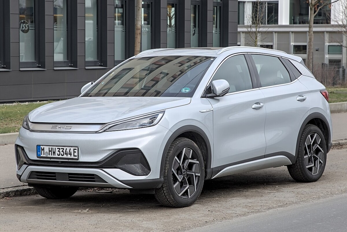
The BYD ATTO 3 is a battery-electric SUV sold in Europe since 2022. This guide covers the 2022-2024 European left-hand-drive fuse arrangement documented in the BYD ATTO 3 EN_V3 owner’s manual from December 2023 and the 2024 manual. Both list two low-voltage fuse boxes: 01-31 behind the dashboard and F1-F53 under the bonnet.
Use only the fuse assignments and ratings for your specific model year, market and electrical options. BYD may change the fuse list while retaining a similar external fuse-box location. The separate 2025 European owner’s manual confirms the general locations but does not repeat the full printed F1-F53 and 01-31 tables, so the 2022-2024 assignments should not automatically be used for later versions or ATTO 3 EVO.
Where are the BYD ATTO 3 fuse boxes?
Cabin (dashboard PDB): on European left-hand-drive cars, behind the lower left dashboard trim on the driver’s side. The numbered positions use two-digit designations 01-31, not F-prefixed positions.
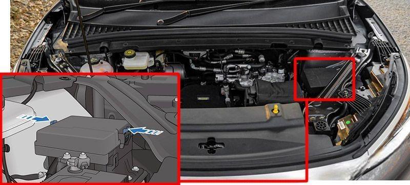
Front compartment (under-hood PDB): toward the rear left of the front compartment, protected by a plastic panel. The front distribution assembly includes positions F1-F53 and some relays identified in the original diagram. Do not assume the passenger compartment and front panel use the same position numbering.
| Fuse box | Location | Fuse positions |
|---|---|---|
| Dashboard PDB | Lower left dashboard behind the driver-side trim on LHD cars | 01-31 |
| Under-hood PDB | Rear left of the front compartment beneath the protective panel | F1-F53 plus the relays shown in the diagram |
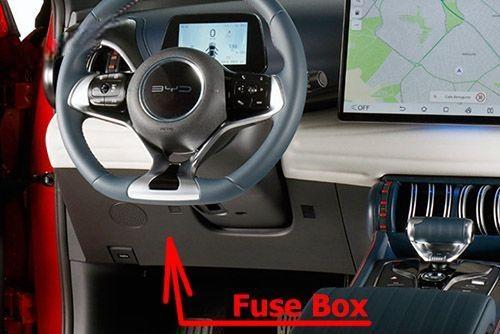
Switch off the car and electrical loads before opening a user-accessible fuse box. Consult the inside cover and use a fuse of exactly the installed type and rated current.
BYD ATTO 3 dashboard fuse box 01-31
The dashboard PDB protects body controllers, the instrument cluster, communications, ADAS, multimedia, OBD diagnostics, on-board charging controls and electrically adjustable front seats. The list preserves the manufacturer’s leading zeros and unused positions.
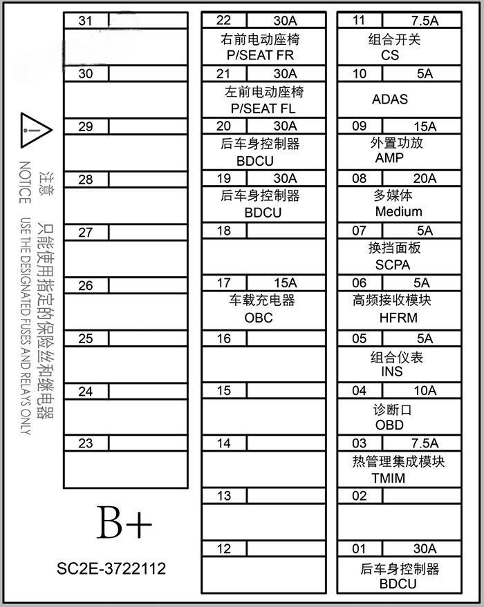
| Position | Amperage [A] | Protected circuit / function |
|---|---|---|
| 01 | 30 A | Rear body controller |
| 02 | – | Unused position |
| 03 | 7.5 A | Integrated thermal management module |
| 04 | 10 A | OBD diagnostic connector |
| 05 | 5 A | Instrument cluster |
| 06 | 5 A | High-frequency receiver module |
| 07 | 5 A | Gear selection panel |
| 08 | 20 A | Multimedia system |
| 09 | 15 A | External audio amplifier |
| 10 | 5 A | Advanced driver assistance systems (ADAS) |
| 11 | 7.5 A | Combination switch |
| 12 | – | Unused position |
| 13 | – | Unused position |
| 14 | – | Unused position |
| 15 | – | Unused position |
| 16 | – | Unused position |
| 17 | 15 A | On-board charger (OBC) |
| 18 | – | Unused position |
| 19 | 30 A | Rear body controller |
| 20 | 30 A | Rear body controller |
| 21 | 30 A | Left front electrically adjustable seat |
| 22 | 30 A | Right front electrically adjustable seat |
| 23 | – | Unused position |
| 24 | – | Unused position |
| 25 | – | Unused position |
| 26 | – | Unused position |
| 27 | – | Unused position |
| 28 | – | Unused position |
| 29 | – | Unused position |
| 30 | – | Unused position |
| 31 | – | Unused position |
Position 17 (15 A) is the on-board charger (OBC), which manages part of the vehicle’s charging electronics. It does not refer to the phone charger or USB ports. The multimedia unit uses 08 (20 A), the audio amplifier uses 09 (15 A), and the diagnostic connector uses 04 (10 A).
BYD ATTO 3 front compartment fuse box F1-F53
The front PDB houses protection for electric PTC heating, low-voltage feeds to high-voltage control modules, the electric air-conditioning compressor, front and rear wipers, the heated rear window, USB ports, accessory sockets, stability control, airbags and steering electronics.
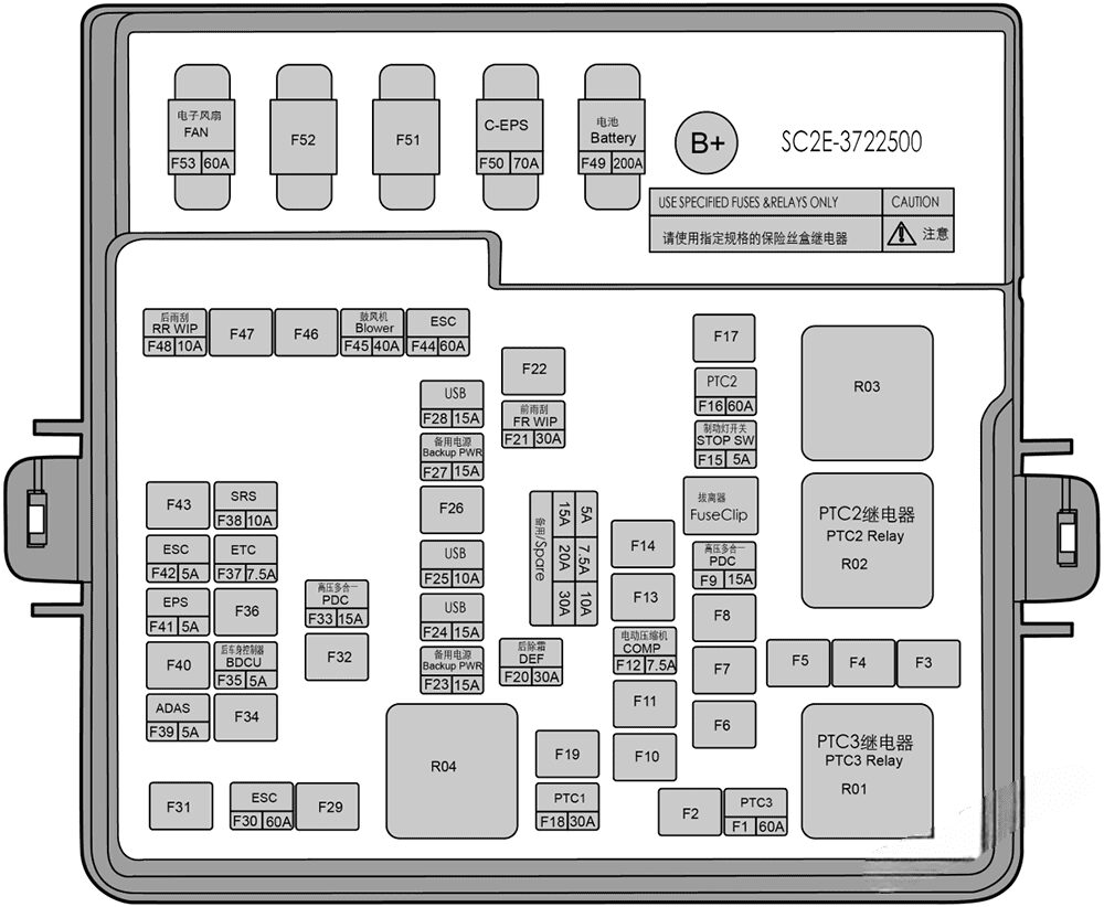
| Position | Amperage [A] | Protected circuit / function |
|---|---|---|
| F1 | 60 A | PTC3 electric heater circuit |
| F2 | – | Unused position |
| F3 | – | Unused position |
| F4 | – | Unused position |
| F5 | – | Unused position |
| F6 | – | Unused position |
| F7 | – | Unused position |
| F8 | – | Unused position |
| F9 | 15 A | Integrated high-voltage control unit low-voltage supply |
| F10 | – | Unused position |
| F11 | – | Unused position |
| F12 | 7.5 A | Electric air-conditioning compressor |
| F13 | – | Unused position |
| F14 | – | Unused position |
| F15 | 5 A | Brake lamp switch |
| F16 | 60 A | PTC2 electric heater circuit |
| F17 | – | Unused position |
| F18 | 30 A | PTC1 electric heater circuit |
| F19 | – | Unused position |
| F20 | 30 A | Rear window defogger |
| F21 | 30 A | Front windscreen wipers |
| F22 | – | Unused position |
| F23 | 15 A | Accessory power socket |
| F24 | 15 A | USB ports |
| F25 | 10 A | USB ports |
| F26 | – | Unused position |
| F27 | 15 A | Accessory power socket |
| F28 | 15 A | USB ports |
| F29 | – | Unused position |
| F30 | 60 A | Electronic Stability Control (ESC) |
| F31 | – | Unused position |
| F32 | – | Unused position |
| F33 | 15 A | Integrated high-voltage control unit low-voltage supply |
| F34 | – | Unused position |
| F35 | 5 A | Rear body controller |
| F36 | – | Unused position |
| F37 | 7.5 A | ETC – manufacturer’s original designation |
| F38 | 10 A | Supplemental Restraint System (SRS) airbags |
| F39 | 5 A | Advanced driver assistance systems (ADAS) |
| F40 | – | Unused position |
| F41 | 5 A | Electric Power Steering (EPS) |
| F42 | 5 A | Electronic Stability Control (ESC) |
| F43 | – | Unused position |
| F44 | 60 A | Electronic Stability Control (ESC) |
| F45 | 40 A | Cabin heating and air conditioning blower |
| F46 | – | Unused position |
| F47 | – | Unused position |
| F48 | 10 A | Rear window wiper |
| F49 | 200 A | Main low-voltage battery power distribution link |
| F50 | 70 A | Column-mounted electric power steering (C-EPS) |
| F51 | – | Unused position |
| F52 | – | Unused position |
| F53 | 60 A | Electric cooling fan |
The original drawing also shows relay positions, including R01-R04 and some PTC heater relays. Because the owner’s manual does not publish a complete named assignment for every relay, this guide does not invent their functions.
BYD ATTO 3 12 V outlets, USB and commonly searched fuses
BYD identifies two accessory power outlet circuits: F23 and F27, both 15 A. The owner’s fuse chart does not state that one is the front socket and the other the rear socket, so these assignments must be checked against the fitted equipment rather than guessed.
USB circuits are protected by F24 (15 A), F25 (10 A) and F28 (15 A). They are not the same circuit as the vehicle’s OBC or the main accessory outlets.
| Circuit / system | Fuse position | Amperage [A] | Box |
|---|---|---|---|
| Accessory power socket | F23 | 15 A | Front compartment |
| Second accessory power socket | F27 | 15 A | Front compartment |
| USB ports | F24 | 15 A | Front compartment |
| USB ports | F25 | 10 A | Front compartment |
| USB ports | F28 | 15 A | Front compartment |
| Multimedia system | 08 | 20 A | Passenger compartment |
| Audio amplifier | 09 | 15 A | Passenger compartment |
| OBD diagnostic connector | 04 | 10 A | Passenger compartment |
| Front windscreen wipers | F21 | 30 A | Front compartment |
| Rear window wiper | F48 | 10 A | Front compartment |
| Rear window defogger | F20 | 30 A | Front compartment |
| Cabin blower | F45 | 40 A | Front compartment |
| Airbag SRS system | F38 | 10 A | Front compartment |
| Driver assistance (ADAS) | F39 and 10 | 5 A and 5 A | Front compartment / passenger compartment |
High-voltage electronics and charging safety
The ATTO 3’s F1-F53 panel contains ordinary low-voltage control and distribution fuses, including some circuits that power high-voltage system controllers. That does not mean the box is itself a user-serviceable high-voltage traction fuse panel. Never touch orange traction cables or open a high-voltage enclosure.
PTC electric heater circuits appear at front F1 (60 A), F16 (60 A) and F18 (30 A). The on-board charger uses cabin 17 (15 A), while integrated high-voltage control unit auxiliary circuits include F9 (15 A) and F33 (15 A). High-current links such as F49 (200 A) require specialist attention.
Differences between BYD ATTO 3 model years
The detailed circuit lists here are grounded in the 2023 EN_V3 and 2024 ATTO 3 manuals. Check the actual fuse-box label if the vehicle was produced in 2025 or later, or has a revised specification. These positions must not be transferred to the BYD Seal U EV, Seal U DM-i or other BYD vehicles.
For other compact electric cars available in Europe, see the MG4 Electric fuse diagrams, Renault Megane E-Tech Electric and Volkswagen ID.3. Their electrical systems use entirely different fuse numbering.
BYD ATTO 3 fuse box FAQ
Where is the dashboard fuse panel?
Under the lower left side of the dashboard on European left-hand-drive models, behind a trim cover. Its positions run from 01 to 31.
Which fuses supply the 12 V accessory sockets?
The front PDB lists F23 (15 A) and F27 (15 A). The general fuse chart does not identify their precise physical sockets.
Which fuses protect the USB ports?
Front-compartment F24 (15 A), F25 (10 A) and F28 (15 A).
Where is the on-board charger fuse?
The low-voltage control circuit for the OBC is dashboard position 17 (15 A) in the documented European layout.
Can I use the same layout for a 2025 ATTO 3 or ATTO 3 EVO?
Not without verifying the vehicle’s specific fuse box diagram and owner’s documentation. A similar box location does not prove the assignments are identical.
Fuse information: BYD ATTO 3 EN_V3 owner’s manual (December 2023) and 2024 model documentation. Featured vehicle photograph: Alexander Migl, Wikimedia Commons, CC BY-SA 4.0.