
The Ford Galaxy Mk2 (2006-2014) has three main electrical fuse boxes: an engine-bay distribution box, a passenger-side dashboard fuse panel and a rear luggage-compartment carrier. Its options include the electric parking brake, heated windscreen, electric seats, rear climate control, adaptive lighting, trailer electrics, keyless entry and extra entertainment systems.
For accurate fuse assignments, Ford divides the Galaxy/S-Max electrical system at 8 February 2010. Vehicles built through 7 February 2010 use the earlier layout; vehicles built from 8 February 2010 use a revised arrangement. The central panel changes from 28 to 24 fuse positions and key circuits are moved. Always confirm the actual vehicle build date and fuse-panel layout.
Where are the Ford Galaxy Mk2 fuse boxes?
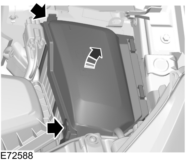
Under-bonnet box: switch off the ignition, lift the bonnet and release the protective cover near the battery. This housing protects engine control, ABS, starter, windscreen heating, wipers, cooling fans and major feeds for the other electrical panels.
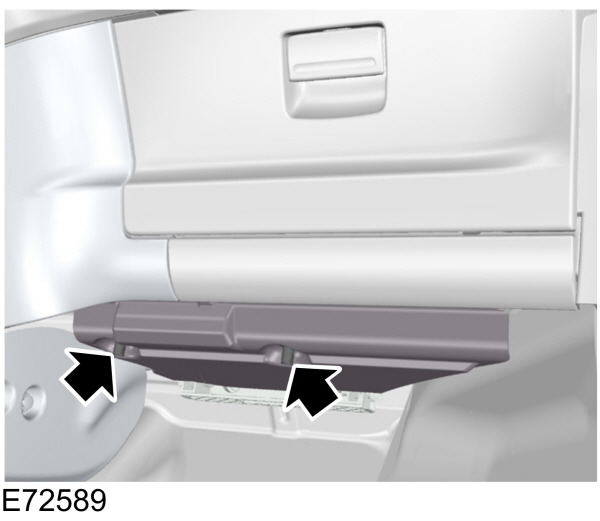
Central box: access the area beneath the passenger-side dashboard. Release the cover clips, remove the cover, turn the mounting knob through 90 degrees and carefully lower the fuse box from its bracket. Its layout differs between the early F1-F28 panel and the revised F1-F24 panel.
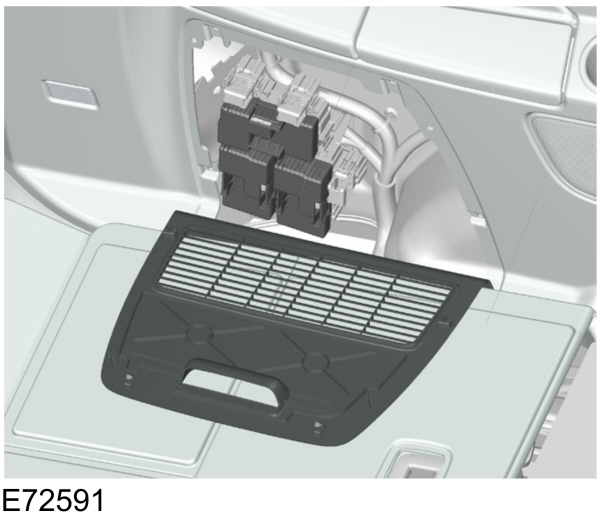
Rear box: release the side trim access cover in the luggage compartment. The FA, FB and FC sections supply door modules, electric seats, parking brake, rear air conditioning, trailer connections, keyless electronics and media equipment.
Which fuse layout applies to your Galaxy?
Built up to 7 February 2010: use the first three fuse-box tables below. The early central fuse F19 (15 A) protects the cigarette lighter and F22 protects the fuel pump, with an alternative rating for the specified 2.2 Duratorq.
Built from 8 February 2010: the later central cigarette lighter moves to F7 (20 A), while the fuel pump is listed at F13. The later electrical layout also covers EcoBoost, Stage V TDCi and Start-Stop configurations.
Engine compartment fuse box – built before 8 February 2010
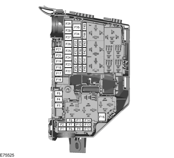
The under-bonnet box contains F1-F45. The high-current F3 fuse has different uses depending on the engine, including twin cooling fans on the 2.3 Duratec-HE and electrohydraulic power steering on the 2.0 TDCi.
| Pozycja | Amperaż [A] | Chroniony obwód / funkcja |
|---|---|---|
| F1 | 10 | Transmission control module |
| F2 | 5 | Diesel glow plug monitoring |
| F3 | 70 | Twin engine cooling fan on 2.3 Duratec-HE |
| F3 | 80 | Electrohydraulic power steering (EHPAS) on 2.0 Duratorq-TDCi |
| F4 | 60 | Glow plugs |
| F5 | 60 | Engine cooling fan |
| F6 | 10 | Oxygen sensors, variable valve timing, catalyst monitoring and lambda sensors, depending on engine |
| F7 | 5 | Relay coils |
| F8 | 10 | Powertrain control module (PCM) |
| F9 | 10 | MAF sensor, swirl control, fuel injectors, crankcase breather heating and variable valve timing, depending on engine |
| F10 | 10 | Engine control unit |
| F11 | 10 | PCV, EGR, VCV, variable valve timing and other engine management valves / sensors |
| F12 | 10 | EGR throttle, turbocharger control, ignition coils or evaporative purge, depending on engine |
| F13 | 15 | Air-conditioning relay |
| F14 | 15 | Diesel fuel filter heater |
| F15 | 40 | Starter relay |
| F16 | 80 | Diesel PTC auxiliary heater |
| F17 | 60 | Central fuse box supply A |
| F18 | 60 | Central fuse box supply B |
| F19 | 60 | Rear fuse box supply C |
| F20 | 60 | Rear fuse box supply D |
| F21 | – | Unused position |
| F22 | 30 | Front wiper control module |
| F23 | 25 | Heated rear window |
| F24 | 30 | Headlamp washers |
| F25 | 30 | ABS hydraulic valves |
| F26 | 40 | ABS pump |
| F27 | 30 | Fuel-fired auxiliary heater |
| F28 | 40 | Heater blower motor |
| F29 | – | Unused position |
| F30 | – | Unused position |
| F31 | 15 | Horn |
| F32 | 5 | Fuel-fired auxiliary heater remote control |
| F33 | 5 | Light switch module and engine-bay fuse box relay coils |
| F34 | 40 | Heated windscreen, left half |
| F35 | 40 | Heated windscreen, right half |
| F36 | 5 | ABS system |
| F37 | 10 | Heated windscreen washer jets |
| F38 | 5 | Adaptive cruise control (ACC) |
| F39 | 15 | Adaptive front lighting system (AFS) |
| F40 | – | Unused position |
| F41 | 20 | Instrument cluster |
| F42 | 10 | Ignition-switched PCM, transmission and EHPAS feed |
| F43 | 5 | Headlamp levelling and AFS |
| F44 | – | Unused position |
| F45 | 15 | Rear window wiper |
Passenger compartment fuse box F1-F28 – built before 8 February 2010
The older dashboard panel has 28 positions. The fuse for the cigarette lighter is F19 (15 A), and the engine-specific fuel pump supply is F22 (20 A or 7.5 A). Compare the actual carrier with the illustration before changing a fuse.
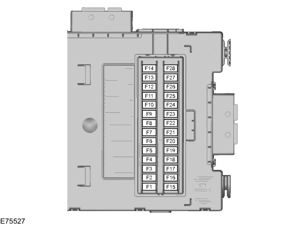
| Pozycja | Amperaż [A] | Chroniony obwód / funkcja |
|---|---|---|
| F1 | 5 | Rain sensor |
| F2 | 10 | SRS / airbag system |
| F3 | 7.5 | ESP yaw-rate sensor and accelerator pedal position sensor |
| F4 | 7.5 | Electronic power supply |
| F5 | – | Unused position |
| F6 | 15 | Audio system with voice commands |
| F7 | 7.5 | Steering wheel control module |
| F8 | 5 | Instrument cluster |
| F9 | 15 | High beam headlamps |
| F10 | 20 | Electric sunroof |
| F11 | 7.5 | Reverse lamps |
| F12 | – | Unused position |
| F13 | 15 | Front fog lamps |
| F14 | 15 | Windscreen washer |
| F15 | 10 | Adaptive cruise control (ACC) |
| F16 | – | Unused position |
| F17 | 10 | Interior lighting |
| F18 | 5 | Engine immobiliser |
| F19 | 15 | Cigarette lighter |
| F20 | – | Unused position |
| F21 | 5 | Remote receiver and interior motion detector |
| F22 | 20 | Fuel pump |
| F22 | 7.5 | Fuel pump on 2.2 Duratorq |
| F23 | – | Unused position |
| F24 | 5 | Ignition switch |
| F25 | 10 | Fuel filler flap |
| F26 | 5 | Battery-backed alarm siren and OBD-II socket |
| F27 | 5 | Steering column and climate control unit |
| F28 | 5 | Brake light switch |
Rear luggage compartment fuse box – built before 8 February 2010
This earlier FA/FB/FC arrangement includes heated seats, rear entertainment and the seat memory system, with separate circuits for electric door and mirror modules. Several positions were moved during the 2010 revision.
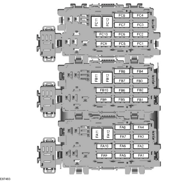
| Pozycja | Amperaż [A] | Chroniony obwód / funkcja |
|---|---|---|
| FA1 | 25 | Left front door module, window, central locking, heated and folding mirror |
| FA2 | 25 | Right front door module, window, central locking, heated and folding mirror |
| FA3 | 25 | Left rear door window module |
| FA4 | 25 | Right rear door window module |
| FA5 | 10 | Rear locking without rear-door modules |
| FA6 | 15 | Auxiliary power outlet |
| FA7 | 5 | Relay coils |
| FA8 | 20 | Steering column lock |
| FA9 | – | Unused position |
| FA10 | 30 | Power-adjustable driver seat |
| FA11 | 20 | Accessories and trailer module |
| FA12 | – | Unused position |
| FB1 | 5 | Parking assistance controller |
| FB2 | 15 | Suspension control unit |
| FB3 | 15 | Heated driver seat |
| FB4 | 15 | Heated front passenger seat |
| FB5 | 15 | Left rear seat heating |
| FB6 | – | Unused position |
| FB7 | 15 | Right rear seat heating |
| FB8 | – | Unused position |
| FB9 | 30 | Power-adjustable passenger seat |
| FB10 | 10 | Anti-theft alarm siren |
| FB11 | – | Unused position |
| FB12 | – | Unused position |
| FC1 | – | Unused position |
| FC2 | – | Unused position |
| FC3 | – | Unused position |
| FC4 | – | Unused position |
| FC5 | 7.5 | Rear-seat CD changer and audio / video equipment |
| FC6 | – | Unused position |
| FC7 | 5 | Seat position memory controller |
| FC8 | 20 | Keyless access system |
| FC9 | – | Unused position |
| FC10 | – | Unused position |
| FC11 | – | Unused position |
| FC12 | – | Unused position |
Engine compartment fuse box – built from 8 February 2010
The revised electrical system supports more engine and transmission variants, including MPS6 PowerShift, EcoBoost SCTi and Stage V Duratorq-TDCi. The same physical box style can conceal different fuse ratings and circuits: the alternatives below must not be treated as interchangeable.
| Pozycja | Amperaż [A] | Chroniony obwód / funkcja |
|---|---|---|
| F1 | 10 | AWF21 automatic transmission control module |
| F1 | 15 | MPS6 PowerShift transmission control module |
| F2 | 5 | Diesel glow plug monitoring |
| F2 | 5 | Auxiliary heater vaporiser glow plug monitoring on 2.0 and 2.2 Duratorq-TDCi Stage V |
| F3 | 70 | Dual cooling fan on 2.3 Duratec-HE and automatic 2.2 Duratorq-TDCi |
| F3 | 80 | Electrohydraulic steering (EHPAS) on 1.6/2.0 EcoBoost SCTi and 1.6/2.0 TDCi Stage V |
| F4 | 60 | Diesel glow plugs |
| F5 | 60 | Cooling fan on specified TDCi, Duratec and 2.0 EcoBoost engines |
| F5 | 70 | Twin cooling fan on 1.6 EcoBoost SCTi |
| F6 | 7.5 | Oxygen sensor on 1.6 Duratorq-TDCi |
| F6 | 10 | Lambda sensors and CMS sensor, depending on engine |
| F6 | 20 | Auxiliary heater vaporiser glow plug on 2.0 and 2.2 TDCi Stage V |
| F7 | 5 | Relay coils |
| F8 | 10 | PCM, fuel metering unit, MAF sensor and fuel rail pressure valve, depending on engine |
| F8 | 20 | PCM on 2.0 EcoBoost SCTi and 2.0 TDCi Stage V |
| F8 | 15 | PCM on 1.6 EcoBoost SCTi, 1.6 TDCi and 2.2 TDCi Stage V |
| F9 | 10 | MAF sensor and injectors, depending on engine |
| F9 | 5 | Auxiliary heater fuel pump on 2.0 TDCi Stage V |
| F9 | 7.5 | MAF, EGR bypass and auxiliary heater pump on 2.2 TDCi Stage V |
| F9 | 7.5 | Vent valve, TMAF sensor, active air shutter, bypass valve, auxiliary heater and coolant pump on 1.6 EcoBoost SCTi |
| F10 | 10 | Engine controller on 2.0 Duratorq-TDCi |
| F10 | 7.5 | Auxiliary heater and coolant pump on 1.6 EcoBoost SCTi |
| F11 | 10 | PCV / VCV / EGR valves, variable valve timing and engine control sensors, depending on engine |
| F11 | 10 | Turbocharger controls, MAF, active air shutter, EGR and VCV on 1.6 Duratorq-TDCi |
| F11 | 5 | MAF, water-in-fuel sensor, active shutter and metering valve on 2.0 TDCi Stage V |
| F11 | 7.5 | Fuel-rail pressure sensor, fuel metering and active shutter on 2.2 TDCi Stage V |
| F11 | 10 | Turbocharger control, variable valve timing, evaporative purge and electric bypass valve on 1.6 EcoBoost SCTi |
| F12 | 10 | Coil-on-plug ignition, purge valve and power steering pressure sensor, engine dependent |
| F12 | 10 | EGR throttle and variable geometry turbo control on 2.0 Duratorq-TDCi |
| F12 | 5 | Relay coils on 1.6 TDCi, 2.0 TDCi Stage V and 2.2 TDCi Stage V |
| F12 | 15 | Ignition coils on 1.6 and 2.0 EcoBoost SCTi |
| F13 | 15 | Air conditioning |
| F14 | 15 | Diesel fuel filter heater on relevant 1.6/2.0 TDCi engines |
| F14 | 10 | Oxygen sensors on 2.2 Duratorq-TDCi Stage V |
| F15 | 40 | Starter relay |
| F16 | 80 | Diesel PTC supplementary heater |
| F17 | 60 | Central fuse box supply A |
| F18 | 60 | Central fuse box supply B |
| F19 | 60 | Rear fuse box supply C |
| F20 | 60 | Rear fuse box supply D |
| F21 | 30 | Cluster, audio, air conditioning and FLR, according to VQM equipment |
| F22 | 30 | Front wiper controller |
| F23 | 25 | Heated rear window |
| F24 | 30 | Headlamp washer |
| F25 | 30 | ABS valves |
| F26 | 40 | ABS pump |
| F27 | 25 | Fuel-fired auxiliary heater |
| F28 | 40 | Heater blower |
| F29 | – | Unused position |
| F30 | 5 | Permanent ABS feed |
| F31 | 15 | Horn |
| F32 | 5 | Fuel-fired heater remote control |
| F33 | 5 | Light switch module and engine fuse box relay coils |
| F34 | 40 | Heated windscreen, left side |
| F35 | 40 | Heated windscreen, right side |
| F36 | 15 | Rear wiper ignition supply |
| F37 | 7.5 | Heated washer jets, FLR and FSM terminal 15 |
| F38 | 10 | PCM, TCM and EHPAS ignition supply |
| F39 | 15 | Adaptive front lighting (AFS) |
| F40 | 5 | Headlamp levelling and AFS module |
| F41 | 20 | Instrument cluster |
| F42 | 5 | Instrument cluster |
| F43 | 15 | Audio module, BVC and DAB module |
| F44 | 5 | Automatic or manual climate control |
| F45 | 5 | Start-stop / FLR system |
Passenger compartment fuse box F1-F24 – built from 8 February 2010
The revised central fuse box contains 24 positions rather than 28. Here the front cigarette lighter is F7 (20 A), while F19 (7.5 A) protects ABS/ESC-related electronics and the electric parking brake. The diagram depicts both left- and right-hand-drive mounting orientations.
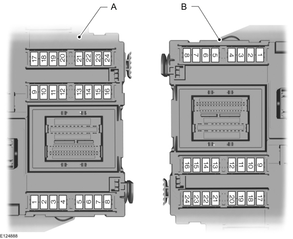
| Pozycja | Amperaż [A] | Chroniony obwód / funkcja |
|---|---|---|
| F1 | 7.5 | Steering wheel control module |
| F2 | 5 | Instrument cluster |
| F3 | 10 | Interior lights |
| F4 | 5 | Engine immobiliser |
| F5 | 7.5 | Adaptive cruise control (ACC) |
| F6 | 5 | Rain sensor |
| F7 | 20 | Cigarette lighter |
| F8 | 10 | Fuel filler flap unlocking |
| F9 | 15 | Rear-window washer |
| F10 | 15 | Front windscreen washer |
| F11 | 10 | Boot lid / tailgate unlocking |
| F12 | 10 | Fuel filler flap locking |
| F13 | 20 | Fuel pump |
| F13 | 7.5 | Fuel pump on 2.2 Duratorq-TDCi Stage V |
| F14 | 5 | Remote-control receiver and interior movement sensor |
| F15 | 5 | Ignition switch |
| F16 | 5 | Battery-backed alarm siren and OBD-II connector |
| F17 | 5 | Steering wheel vibration actuator |
| F18 | 10 | SRS / airbag system |
| F19 | 7.5 | ABS, yaw-rate sensor / ESC, electric parking brake and accelerator pedal supply |
| F20 | 7.5 | Electronic supply, auto-dimming mirror and lane departure warning |
| F21 | 15 | Radio supply |
| F22 | 5 | Brake light switch |
| F23 | 20 | Sunroof |
| F24 | 5 | Climate control and steering-column module |
Rear luggage compartment fuse box – built from 8 February 2010
The later FA/FB/FC configuration contains revised keyless, Start-Stop and BLIS feeds, along with additional rear air-conditioning and EPB protection. Ford lists 30 A circuits at FC2 and FC3 for the electric parking brake on applicable vehicles.
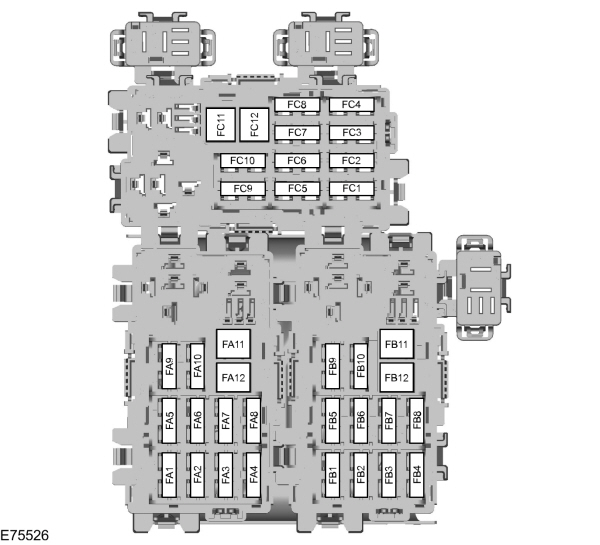
| Pozycja | Amperaż [A] | Chroniony obwód / funkcja |
|---|---|---|
| FA1 | 25 | Left front door module: window, central locking, folding / heated mirror |
| FA2 | 25 | Right front door module: window, central locking, folding / heated mirror |
| FA3 | 25 | Left rear door window module |
| FA4 | 25 | Right rear door window module |
| FA5 | 10 | Rear locking without rear-door control modules |
| FA6 | 15 | Auxiliary power outlet |
| FA7 | 5 | Relay coils |
| FA8 | 20 | Keyless vehicle system module |
| FA9 | 5 | VQM relay coils for Start-Stop |
| FA10 | – | Unused position |
| FA11 | 20 | Accessories and trailer module |
| FA12 | 30 | Power-adjustable driver seat |
| FB1 | 15 | Sunblind system |
| FB2 | 15 | Suspension controller |
| FB3 | 15 | Heated driver seat |
| FB4 | 15 | Heated front passenger seat |
| FB5 | – | Unused position |
| FB6 | 10 | Rear climate control |
| FB7 | – | Unused position |
| FB8 | 5 | Parking aid and BLIS monitoring |
| FB9 | 30 | Power-adjustable front passenger seat |
| FB10 | 10 | Anti-theft alarm siren |
| FB11 | – | Unused position |
| FB12 | – | Unused position |
| FC1 | 7.5 | Powered rear quarter windows |
| FC2 | 30 | Electric parking brake (EPB) |
| FC3 | 30 | Electric parking brake (EPB) |
| FC4 | 10 | Rear air conditioning |
| FC5 | 20 | Keyless entry and starting system |
| FC6 | 20 | Rear climate-control blower |
| FC7 | 5 | Seat memory controller |
| FC8 | 7.5 | Rear-seat entertainment and CD changer |
| FC9 | 20 | Audio amplifier |
| FC10 | 10 | Sony Audiophile system |
| FC11 | – | Unused position |
| FC12 | – | Unused position |
Engine and transmission-specific fuse ratings
Several positions use two ratings because the fitted consumer is different on another powertrain. In the following summary the position is restricted to the short fuse code, and the engine or gearbox variant is described in the final column.
| Pozycja | Amperaż [A] | Chroniony obwód / funkcja |
|---|---|---|
| F1 | 10 | AWF21 automatic transmission controller |
| F1 | 15 | MPS6 PowerShift transmission controller |
| F3 | 70 | Twin cooling fans on 2.3 Duratec-HE or 2.2 TDCi automatic |
| F3 | 80 | Electrohydraulic power steering (EHPAS) on selected EcoBoost and Stage V TDCi |
| F5 | 60 | Engine cooling fan on most versions |
| F5 | 70 | Twin radiator fans on 1.6 EcoBoost |
| F13 | 20 | Fuel pump on most later models |
| F13 | 7.5 | Fuel pump on 2.2 Duratorq-TDCi Stage V |
At the under-bonnet F1 position, an AWF21 automatic gearbox uses 10 A, while MPS6 PowerShift uses 15 A. At F3, selected versions use 70 A for twin cooling fans or 80 A for EHPAS. The revised central F13 fuel-pump rating is also engine dependent.
High-current feeds to central and rear fuse boxes
Ford does not provide a universal owner-facing identification table for every relay in the Galaxy engine bay, so relay functions must not be guessed from physical positions. The main distribution fuses are documented and can be checked if several unrelated electrical systems lose power simultaneously.
| Pozycja | Amperaż [A] | Chroniony obwód / funkcja |
|---|---|---|
| F17 | 60 | Central fuse box feed A |
| F18 | 60 | Central fuse box feed B |
| F19 | 60 | Rear fuse box feed C |
| F20 | 60 | Rear fuse box feed D |
In addition, F7 (5 A) in the engine bay supplies relay coils, F15 (40 A) protects the starter relay feed and F33 (5 A) serves the lighting switch module and engine-box relay coils. These are not the same as similarly numbered fuses in the dashboard panel.
Common Ford Galaxy Mk2 fuse problems
Front cigarette lighter has no power: check central F19 (15 A) on vehicles built through 7 February 2010 or F7 (20 A) on vehicles built from 8 February 2010. Unplug the accessory and inspect the socket for debris before replacing a fuse.
Electric parking brake warning: on the revised rear box examine FC2 and FC3 (30 A each) as well as the electronic control feed at central F19 (7.5 A). A failed fuse is only one of several possible causes, so read the fault codes and check supply connections.
Only one side of the heated windscreen works: the two halves are protected independently by under-bonnet F34 and F35 (40 A each). Check the corresponding wiring and heating element as well.
Rear climate blower inoperative: check the rear FC6 supply (20 A) and FC4 control (10 A) in the later configuration. The earlier installation has a different rear arrangement.
Several devices lose power at once: the main F17-F20 (60 A) supplies feed the central and rear fuse boxes. High-current faults require proper electrical testing; never replace a fusible link with wire or increase its rating.
The Galaxy shares a platform with the Ford S-Max Mk1 and Mondeo Mk4, but equipment allocations are not fully interchangeable. Ford’s original owner manual and fuse box legend for the vehicle take precedence over a general diagram.