The Mitsubishi Lancer X (CY/CX, 2007-2017) has three electrical protection areas: the main engine-bay fuse box, a separate set of high-current fusible links at the battery and a passenger-compartment fuse board. This guide retains all 32 main engine fuses, relay slots A-11X to A-30X, battery links 33-37, and 25 passenger fuses plus relay R1. Equipment affects allocation, including turbo and diesel engines, CVT and SST transmissions, and unused relay sockets.
Where are the three Mitsubishi Lancer X fuse panels?
Main under-bonnet box: Switch the ignition off and raise the bonnet. Locate the large black fuse carrier close to the battery. Depress the cover catch and remove the lid, then match position numbers 1-32 or relay codes A-11X to A-30X with the diagram. Not all relay sockets are equipped on every vehicle.
Battery-mounted links: High-current fusible links 33-37 are housed separately near the positive battery terminal. Their 80 A and 120 A ratings protect major supply circuits. Inspect the battery terminals and associated wiring if power is missing. High-current links require the correct service procedure rather than ordinary blade-fuse replacement.
Passenger compartment: On left-hand-drive Lancer X models, open the driver’s door and remove the lower dashboard access cover. The panel beneath contains fuse positions 1-25 for the outlets, locks, wipers, audio and heated glass. Right-hand-drive locations may differ.
Engine compartment – fuses 1-32 and relays A-11X to A-30X
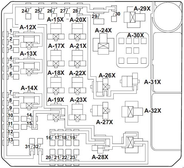
| Pozycja | Amperaż [A] | Chroniony obwód / funkcja |
|---|---|---|
| 1 | 15 | Front fog lamps |
| 2 | 7.5 | Engine control module |
| 3 | 20 | CVT, transmission controller and pulley-speed sensors |
| 4 | 10 | Horn |
| 5 | 7.5 | Alternator control |
| 6 | 20 | Headlamp washers |
| 7 | 10 | Air-conditioning compressor |
| 8 | 15 | Electronic throttle valve (ETV) and SST transmission oil cooling, according to engine |
| 9 | 20 | Alarm siren |
| 10 | 15 | Windscreen wiper de-icer |
| 11 | – | Unused position |
| 12 | 30 | Power management module |
| 13 | 10 | Daytime running lights (DRL) |
| 14 | 10 | Left-hand main-beam headlamp |
| 15 | 10 | Right-hand main-beam headlamp |
| 16 | 20 | Left-hand headlamp assembly |
| 17 | 20 | Right-hand headlamp assembly |
| 18 | 10 | Left-hand dipped-beam headlamp |
| 19 | 10 | Right-hand dipped-beam headlamp |
| 20 | 10 | Engine management or intercooler water spray (I/C SPRAY) on turbo versions |
| 21 | 10 | Ignition coils 1-4 |
| 22 | 20 / 25 | Engine ECU, injection, oxygen sensors, EVAP and airflow meter; some diesels also use fuel-line heating |
| 23 | 15 / 20 | Fuel pump: 15 A on naturally aspirated engines, 20 A on turbocharged versions |
| 24 | 30 | Starter motor supply |
| 25 | 40 | Variable valve lift control on non-turbo engine versions |
| 26 | 40 | ABS first supply circuit |
| 27 | 30 | ABS second supply circuit |
| 28 | 30 | Air-conditioning condenser fan |
| 29 | 40 | Engine cooling fan |
| 30 | 30 | IOD supply and passenger fuse positions 7-9 |
| 31 | 30 | Factory audio amplifier |
| 32 | 30 | Additional diesel engine protection circuit |
| A-11X | – | Front fog lamp relay |
| A-12X | – | Horn relay |
| A-13X | – | Air-conditioning compressor clutch relay |
| A-14X | – | Unused relay socket |
| A-15X | – | CVT relay |
| A-16X | – | Unused relay socket |
| A-17X | – | Main-beam headlamp relay |
| A-18X | – | Throttle actuator relay |
| A-19X | – | Unused relay socket |
| A-20X | – | Daytime running light relay |
| A-21X | – | Fuel injector relay |
| A-22X | – | Unused relay socket |
| A-23X | – | Condenser cooling fan relay |
| A-24X | – | Starter relay |
| A-25X | – | Dipped-beam headlamp relay |
| A-26X | – | Engine cooling fan relay |
| A-27X | – | Unused relay socket |
| A-28X | – | Fan control relay |
| A-29X | – | Unused relay socket |
| A-30X | – | Multi-point fuel injection (MFI) main relay |
Battery-mounted fusible links – positions 33-37
These protect upstream distribution to the body electronics, the under-bonnet box and the headlamp relay circuits. Do not substitute a different rating or a conventional small blade fuse for a fusible link.
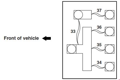
| Pozycja | Amperaż [A] | Chroniony obwód / funkcja |
|---|---|---|
| 33 | 120 | Main power feed for fusible links 34-37 |
| 34 | 80 | Power supply to selected passenger-compartment circuits and ETACS |
| 35 | 80 | Unused 80 A fusible link in this illustrated configuration |
| 36 | 120 | Power feed for engine compartment fuse box and headlamp relays |
| 37 | 80 | Second supply circuit for passenger fuse panel and ETACS module |
Interior fuse box – positions 1-25 and relay R1
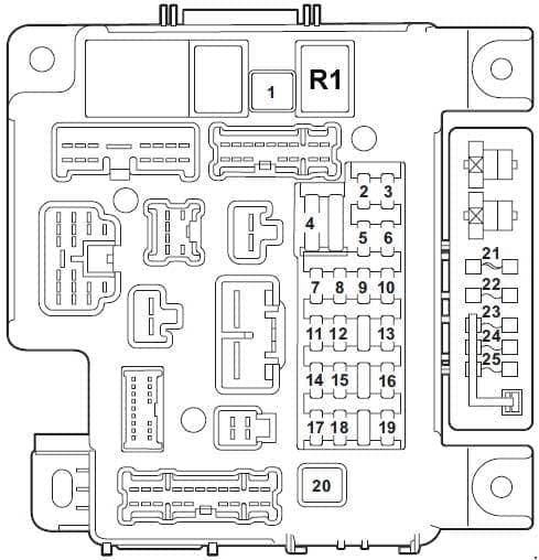
| Pozycja | Amperaż [A] | Chroniony obwód / funkcja |
|---|---|---|
| 1 | 30 | Heating and ventilation blower |
| 2 | 15 | Brake lamps, ETACS and gearbox switch |
| 3 | 10 | Rear fog lamp |
| 4 | 30 | Front windscreen wipers and washers |
| 5 | 10 | OBD diagnostic connector |
| 6 | 20 | Central locking of doors and boot |
| 7 | 15 | Radio, navigation and Bluetooth, depending on equipment |
| 8 | 7.5 | Air conditioning, ETACS, instruments and keyless operation system (KOS) |
| 9 | 15 | Radio, navigation and centre console electronics |
| 10 | 15 | ETACS and hazard warning lamps |
| 11 | 15 | Rear window wiper, where fitted |
| 12 | 7.5 | Air conditioning, ABS, CVT, SRS and keyless entry |
| 13 | 15 | Front cigarette lighter and 12 V outlet |
| 14 | 10 | Ignition switch |
| 15 | 20 | Sunroof, where fitted |
| 16 | 10 | Multimedia equipment and mirror adjustment |
| 17 | 10 | Front passenger seat occupancy sensor |
| 18 | 7.5 | Transmission controls and SRS module |
| 19 | 15 | Rear cabin accessory socket |
| 20 | 30 | Electric windows |
| 21 | 30 | Heated rear window |
| 22 | 7.5 | Exterior mirror adjustment |
| 23 | 15 | 115 V accessory power socket, where fitted |
| 24 | 20 / 25 | Electric seat supply, depending on equipment |
| 25 | 30 | Heated seats |
| R1 | – | Heating and air-conditioning blower relay |
Differences for turbo, diesel, CVT and SST vehicles
Under-bonnet fuse 22 has a 20 A engine-management assignment in some versions or a 25 A supply related to diesel fuel-line heating. Fuse 23 is specified at 15 A for the fuel pump on naturally aspirated petrol models or 20 A on turbocharged variants. Cabin fuse 24 also varies between 20 A and 25 A according to the electric seat installation. These are alternative factory specifications, not permission to fit the higher value to another version.
CVT-equipped vehicles use a dedicated transmission control circuit at engine fuse 3 (20 A). Some SST-equipped variants use part of the engine-bay circuit at position 8 (15 A) for transmission oil cooling. Check the engine and gearbox combination before diagnosing either system.
Cigarette lighter, wipers, ABS and starting
12 V power: The cigarette lighter and front socket are protected by passenger fuse 13 (15 A). The rear accessory outlet has its own fuse 19 (15 A).
Wipers and rear-window demister: Check passenger fuse 4 (30 A) when the front wipers are inoperative, and fuse 21 (30 A) when the rear window does not heat. The rear wiper, where fitted, uses passenger fuse 11 (15 A).
ABS and engine starting: ABS has two engine-bay power circuits, positions 26 (40 A) and 27 (30 A). For a no-crank condition, inspect engine fuse 24 (30 A) and starter relay A-24X as appropriate. Fuel pump fuse 23 must match the naturally aspirated or turbo engine specification. A warning light or failed start can have causes other than a blown fuse, so check diagnostic codes and wiring before replacing components.
Earlier Lancer fuse layout
The previous Mitsubishi Lancer IX CS (2000-2007) has a different main fuse box, additional relays and no identical battery-link arrangement. Use its own diagrams when working on a ninth-generation vehicle.
Technical basis: Mitsubishi Lancer CY/CX 2007-2017 fuse and relay circuit tables covering petrol, turbo, diesel and optional equipment. Confirm the factory label and engine/gearbox configuration before any fuse replacement.