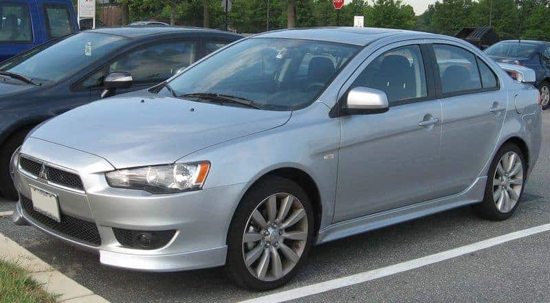
The Mitsubishi Lancer IX (CS series, 2000-2007) has a main engine-compartment fuse box, an additional under-bonnet relay block and a driver’s side interior fuse panel. The tables cover 26 main under-bonnet fuse positions, A-04X to A-11X relay and module sockets, B-10X to B-17X locations, and 20 passenger-compartment fuses with eight interior relays. The Lancer Evolution IX has a different electrical arrangement and should not be diagnosed from this layout.
Where are the Mitsubishi Lancer IX fuse boxes?
Engine compartment: Switch off the ignition, open the bonnet and find the plastic fuse box next to the battery on the left-hand side of the engine compartment. Release the cover clips and compare the printed fuse numbering with the first diagram. A separate nearby relay box contains the B-10X to B-17X positions.
Inside the cabin: Open the driver’s door. On left-hand-drive vehicles the fuse panel sits behind the lower left dashboard trim beneath the steering wheel. Remove the access cover and identify fuse positions 1-20. Relay sockets R1-R8 are located nearby but are not numbered as fuse positions.
Main engine compartment fuse box – positions 1-26 and A-04X to A-11X
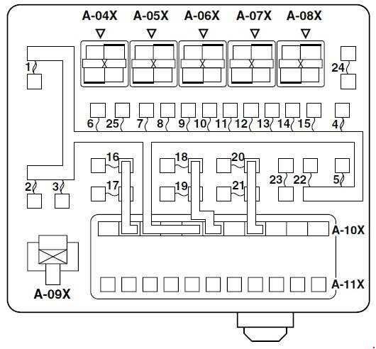
| Pozycja | Amperaż [A] | Chroniony obwód / funkcja |
|---|---|---|
| 1 | 60 | Power supply for cabin fuse circuits 15, 16, 19 and 20 |
| 2 | 50 | Radiator cooling fan controller |
| 3 | 60 | ABS main power supply |
| 4 | 40 | Ignition switch main supply |
| 5 | 30 | Electric window supply |
| 6 | 15 | Front fog lamps and relay |
| 7 | 10 | Horn and horn relay |
| 8 | 20 | Engine ECU, airflow meter, sensors, injectors, EGR, EVAP, immobiliser and associated relays |
| 9 | 10 | Air-conditioning compressor clutch |
| 10 | 15 | ABS and automatic transmission controllers, brake lamps |
| 11 | 15 | Additional 12 V accessory power socket |
| 12 | 7.5 | Alternator control |
| 13 | 10 | Turn indicators, hazard warning lights and ETACS body electronics |
| 14 | 20 | Automatic transmission control |
| 15 | 15 | Fuel pump |
| 16 | 10 | Right-hand main-beam headlamp |
| 17 | 10 | Left-hand main-beam headlamp and warning light |
| 18 | 10 | Right-hand dipped-beam headlamp |
| 19 | 10 | Left-hand dipped-beam headlamp and levelling |
| 20 | 7.5 | Right-hand position lights and interior illumination |
| 21 | 7.5 | Left-hand position lights and dashboard illumination |
| 22 | 10 | Instrument cluster, combination switch and ETACS |
| 23 | 10 | Clock, ETACS and radio connector |
| 24 | – | Unused position |
| 25 | 20 | Heated seats, where fitted |
| 26 | 100 / 120 | Main supply and front electronics module, 100 A on 4G1 engines or 120 A on 4G6 engines; check engine variant |
| A-04X | – | Front fog lamp relay |
| A-05X | – | Horn relay |
| A-06X | – | Unused relay socket |
| A-07X | – | Unused relay socket |
| A-08X | – | Unused relay socket |
| A-09X | – | Cooling fan control relay |
| A-10X | – | Front-ECU module, first slot |
| A-11X | – | Front-ECU module, second slot |
Additional under-bonnet relay box – B-10X to B-17X
These codes identify relay and connector locations rather than blade fuses. B-10X is an engine-speed detection connector, not a relay. Positions without an installed relay are explicitly shown as unused.
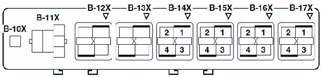
| Pozycja | Amperaż [A] | Chroniony obwód / funkcja |
|---|---|---|
| B-10X | – | Engine speed detection connector – not a relay |
| B-11X | – | Unused socket |
| B-12X | – | Unused socket |
| B-13X | – | Unused socket |
| B-14X | – | Ignition coil relay |
| B-15X | – | Automatic transmission relay |
| B-16X | – | Engine management relay |
| B-17X | – | Air-conditioning compressor clutch relay |
Passenger compartment – fuse positions 1-20 and relays R1-R8
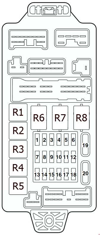
| Pozycja | Amperaż [A] | Chroniony obwód / funkcja |
|---|---|---|
| 1 | 10 | Ignition coils and condenser |
| 2 | 7.5 | ABS, brake, charging, SRS, oil pressure and fuel warning lamps, ETACS and instrument cluster |
| 3 | 7.5 | Automatic transmission and sensors, instrument cluster and SRS |
| 4 | – | Unused position |
| 5 | 7.5 | Air conditioning, blower and rear demister relays, heated seats |
| 6 | 7.5 | Electric door mirrors |
| 7 | 20 | Front windscreen wipers and control module |
| 8 | 7.5 | Engine management and fuel pump relay control |
| 9 | 15 | 12 V cigarette lighter |
| 10 | – | Unused position |
| 11 | 7.5 | Accessory socket relay and mirrors |
| 12 | 7.5 | ABS control module |
| 13 | – | Unused position |
| 14 | 15 | ETACS and rear window wiper, where fitted |
| 15 | 15 | Diagnostic connector |
| 16 | 10 | Rear fog lamp and relay |
| 17 | – | Unused position |
| 18 | – | Unused position |
| 19 | 30 | Cabin blower and heater controls |
| 20 | 30 | Heated rear window |
| R1 | – | Fuel pump relay no. 1 |
| R2 | – | Heated seat relay |
| R3 | – | Fuel pump relay no. 2 |
| R4 | – | Accessory socket relay |
| R5 | – | Rear fog lamp relay |
| R6 | – | Electric window relay |
| R7 | – | Blower relay |
| R8 | – | Rear demister relay |
4G1 and 4G6 engine differences
The Lancer IX range includes engines in the 4G1 and 4G6 families, manual and automatic gearboxes, and equipment variations such as heated seats. Most importantly, main under-bonnet position 26 is specified at 100 A for the indicated 4G1 installation but at 120 A for 4G6 versions. These ratings are not substitutes for one another. Confirm the engine and original fusible link before replacement.
Cigarette lighter, fuel pump and blower troubleshooting
Cigarette lighter and 12 V socket: The cabin lighter uses fuse 9 (15 A). The additional accessory socket uses engine-bay fuse 11 (15 A) and is switched by cabin relay R4, so these sockets can fail independently.
Wipers and ventilation: The front wiper circuit uses cabin fuse 7 (20 A). If the cabin fan is dead, check fuse 19 (30 A) and blower relay R7 before tracing the motor and wiring.
Fuel pump and starting: The pump has engine-bay fuse 15 (15 A), cabin control fuse 8 (7.5 A), and related relays R1 and R3. For rear-window heating, check cabin fuse 20 (30 A) and relay R8. The ABS main power supply uses engine fuse 3 (60 A) and a separate cabin control feed at position 12 (7.5 A).
What changed on the Lancer X?
The successor Mitsubishi Lancer X (2007-2017) uses different fuse and relay layouts and adds a high-current fusible-link assembly at the battery. Fuse numbers on the ninth-generation Lancer should not be transferred to the later car.
Technical basis: Mitsubishi Lancer CS fuse and relay circuit listings for 2000-2007. Always verify market, engine, fitted options and the fuse box cover legend for the individual vehicle.