
Renault Grand Scenic II J84 (2004-2009) is the long-wheelbase, second-generation seven-seat Scenic. Its electrical installation has a passenger fuse/relay box controlled by the UCH body electronics, an under-bonnet protection and switching unit (UPC), separate high-current battery fuses, additional cooling fan protection and equipment-dependent relays. A 1.6 K4M, 2.0 M4R or F4R version may have different power feeds, just as a key-card car can differ from a conventional key and automatic gearbox installation.
These seven complete tables preserve every one of the 104 original fuse, relay and alternative equipment entries. They include all unused positions, the separate 190/300 A engine variants and the distinction between three unrelated relays that each carry the letter C. All seven model-specific original diagrams are retained, directly before the relevant tables. Manufacturer owners’ literature confirms the location of the interior fuse panel and cautions that some engine electrical fuses are intended for dealer servicing.
Where are the Grand Scenic II fuse boxes?
Passenger compartment: with the ignition off and Renault card removed, open the lower left dashboard storage/access panel near the driver’s knee on a left-hand-drive J84. Release its securing catch and move the panel past its retaining stop as described by the owner manual. Read the fuse-symbol card on the inside of the cover before using the puller to remove the correctly numbered fuse. A right-hand-drive car may have another trim arrangement. Do not disturb yellow airbag wiring.
Under the bonnet: the UPC fuse and relay unit is located behind the battery, protected by covers. With ignition and fan off, remove or release the protective trim as required and identify the 1-25 engine fuse positions. Additional high-current links are situated beneath the UPC and around the battery; the engine cooling fan also has its own separate 70 A supply. Access to these carriers can require dismantling nearby components and correct battery isolation. Renault advises professional servicing for less accessible engine fuses.
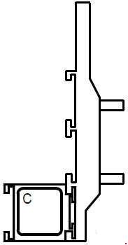
Extra cabin blower relay: on some key-card vehicles with manual air conditioning, a separate 70 A relay is fitted near the lower steering-column/dashboard area. The body-controller relay and this extra relay are physically different components even though both have the letter C in some diagrams.
Passenger compartment – F1-F42 and relay positions A-D
F3 (10 A) protects the first-row cigarette lighter; F4 (10 A) is the second-row accessory outlet on key-card versions. F40 (40 A) supplies the cabin blower, F42 (40 A) the heated rear window, F37 (10 A) all three brake lamps, and F14/F16/F17 (25 A each) the relevant electric window motors. Body UCH circuits have separate feeds and can affect lighting, doors and the tailgate.
The lower portion of this same carrier contains relay A (70 A delayed accessories), relay B (70 A ignition-load reduction or accessories), relay C (40 A rear screen heater) and relay D (20 A horn). Empty positions F1/F2 and other spare locations are retained, not assigned speculative circuits.
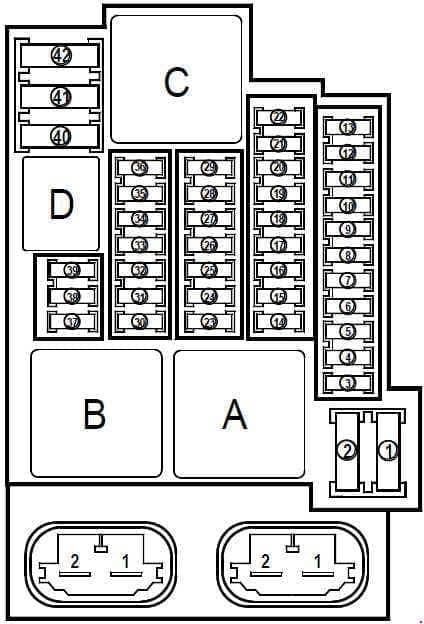
| Pozycja | Amperaż [A] | Chroniony obwód / funkcja |
|---|---|---|
| F1 | – | Unoccupied position |
| F2 | – | Unoccupied position |
| F3 | 10 | Front-row cigarette lighter / 12 V outlet |
| F4 | 10 | Second-row accessories power outlet on vehicles with the Renault key card |
| F5 | – | Unoccupied position |
| F6 | – | Unoccupied position |
| F7 | 5 | Electrically adjustable passenger-side exterior mirror |
| F8 | 10 | Front windscreen washer pump; on key-card cars also the opening-element warning buzzer, and on key-operated cars the optional tracking electronics |
| F9 | – | Unoccupied position |
| F10 | 10 | Instrument cluster, key-card version |
| F11 | – | Unoccupied position |
| F12 | – | Unoccupied position |
| F13 | – | Unoccupied position |
| F14 | 25 | Front passenger electric window motor |
| F15 | 5 | Brake pedal/stop light switch, ABS/ESP controller and wheel-speed input |
| F16 | 25 | Right rear electric window motor |
| F17 | 25 | Left rear electric window motor |
| F18 | 10 | Cabin and luggage compartment courtesy lights, door lamps and rain sensor |
| F19 | 10 | Seat-belt reminder, CAN interface, sound system and optional tracking electronics |
| F20 | 5 | Automatic air conditioning control panel |
| F21 | 10 | Fuel filler flap locking motor |
| F22 | – | Unoccupied position |
| F23 | 20 | Trailer electrical connection module |
| F24 | 15 | Tailgate lock and boot illumination through body controller UCH |
| F25 | – | Unoccupied position |
| F26 | 10 | Navigation control system and related accessories |
| F27 | 20 | Radio/audio unit |
| F28 | – | Unoccupied position |
| F29 | – | Unoccupied position |
| F30 | 15 | Left and right direction indicators and mirror repeaters, controlled by UCH |
| F31 | 10 | UCH body control module electrical supply |
| F32 | 30 | Driver’s door electric control module |
| F33 | 25 | Front/rear door central locking and fuel-filler lock through UCH |
| F34 | – | Unoccupied position |
| F35 | 15 | Radio display, clock, exterior temperature, CAN bus, instrument cluster and tracker on key-operated versions |
| F36 | 15 | On-board diagnostic OBD connector, alarm and horn-relay supply |
| F37 | 10 | Left, right and third brake lights through UCH |
| F38 | – | Unoccupied position |
| F39 | – | Unoccupied position |
| F40 | 40 | Cabin blower motor and speed regulation unit; power switching differs between key card and ignition key |
| F41 | 25 | Electric sunroof, if equipped |
| F42 | 40 | Rear window defogger through relay C and related fuse circuit |
| A | 70 | Relay A – delayed accessory main power supply, 70 A contacts |
| B | 70 | Relay B – load reduction during starting on key-card cars, or accessory power supply with conventional key, 70 A contacts |
| C | 40 | Relay C – heated rear-window relay, 40 A contacts on the main cabin carrier |
| D | 20 | Relay D – horn relay, 20 A contacts on the main cabin carrier |
Separate 70 A blower relay C near steering column
The additional relay C provides heater blower power with the engine running on the key-card and manual-air-conditioning configuration. Its current contact rating is 70 A. This must not be confused with the 40 A rear-screen relay C on the main interior board, or the automatic-transmission 20 A reverse-light relay C in the engine auxiliary unit.
| Pozycja | Amperaż [A] | Chroniony obwód / funkcja |
|---|---|---|
| C | 70 | Additional relay C – 70 A cabin blower power, active with engine running on key-card versions with manual air conditioning; a different relay from cabin carrier C 40 A |
Main engine-bay UPC protection and switching module – all 25 positions
The engine fuse and switching unit mounted behind the battery supplies exterior lights, ABS/ESP, the windscreen wiper motor, engine injection, starter, air-conditioning compressor, gearbox and electric steering-lock circuits. The engine power feed at position 13 (25 A) can cover different K4M, M4R and F4R engine devices, including injection, variable valve timing or throttle electronics. Position 14 (15 A) concerns oxygen sensors and selected variable valve timing circuits.
Automatic gearbox versions may use position 12 (7.5 A) and 15 (20 A), whereas key-card vehicles use position 18 (15 A) for the electric steering-column lock. The reversing-light supply at position 17 (10 A) is linked to the manual gearbox switch or supplementary engine relay C in automatic variants. Check the original UPC cover and full engine code before testing.
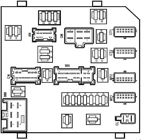
| Pozycja | Amperaż [A] | Chroniony obwód / funkcja |
|---|---|---|
| 1 | 10 | Right and left position lamps, number plate lighting and switch illumination; may also supply front-row 12 V outlet, radio, cruise controls, ESP switch, locking and parking equipment |
| 2 | 10 | Left front/rear position and side lamps |
| 3 | 15 | Headlamp washer pump |
| 4 | 20 | Left and right front fog lamps |
| 5 | 10 | Left headlamp main supply |
| 6 | 10 | Right headlamp main supply |
| 7 | 15 | Diagnostic connector, parking and gearbox electronics, manual A/C, mirror and cruise controls, both headlamp levelling motors and other equipment as fitted |
| 8 | 30 | ABS/ESP control electronics |
| 9 | 30 | Front windscreen wiper motor |
| 10 | 10 | Airbag and seat-belt pretensioner controller; electric steering-column lock on key-card versions |
| 11 | – | Unoccupied position |
| 12 | 7.5 | Automatic gearbox ECU, input/output speed sensors and multifunction transmission switch |
| 13 | 25 | Fuel injection and engine power feed on K4M, M4R and F4R variants: injection valves, camshaft phasing, throttle body, fuel pump and turbo components depending on exact engine |
| 14 | 15 | Oxygen/lambda sensors before and after the catalytic converter, variable valve timing on applicable K4M/M4R/F4R engines |
| 15 | 20 | Automatic transmission control unit |
| 16 | 5 | Brake pedal switch, UCH unit and electric power steering control feed |
| 17 | 10 | Reversing lamps and manual gearbox reverse switch; automatic cars use UPC and supplementary relay C |
| 18 | 15 | Steering column electric lock through UCH on Renault key-card versions |
| 19 | 25 | Starter motor control power feed |
| 20 | – | Unoccupied position |
| 21 | 20 | Fuel pump, fuel gauge and ignition-coil feed on K4M/M4R/F4R engine-specific installations |
| 22 | 10 | Air conditioning compressor electromagnetic clutch |
| 23 | 5 | Engine fuel injection ECU supply |
| 24 | 20 | Left headlamp additional supply branch |
| 25 | 20 | Right headlamp additional supply branch |
Under-UPC high-current block – F1-F6
This separate six-position power carrier distributes 80 A supplies to groups of passenger cabin fuses and the UPC, plus a 50 A ABS/ESP circuit. F1 and F5 are unoccupied on the documented carrier. These are high-current electrical links beneath the UPC, not duplicates of cabin fuses F1-F6. Do not remove bolted fuses with live battery power.
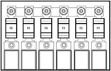
| Pozycja | Amperaż [A] | Chroniony obwód / funkcja |
|---|---|---|
| F1 | – | Unoccupied high-current position |
| F2 | 80 | 80 A supply to cabin fuses F37-F38 and, via relay, F3-F6, F8, F11 and F40 |
| F3 | 80 | 80 A supply to cabin fuses F9, F12, F41 and F42 |
| F4 | 80 | 80 A supply to UPC and cabin fuses F23-F24 and, via relay, F1-F2 and F14-F22 |
| F5 | – | Unoccupied high-current position |
| F6 | 50 | 50 A main ABS/ESP system supply |
Additional engine cooling fan and fuel pump unit – F1-F9 and A-D
On the separately illustrated auxiliary unit, F5 (60 A) controls the engine radiator fan high-speed feed, while F8 (30 A) serves the low-speed resistor/control module. A fuel pump feed F6 (20 A) and relay B (20 A) occur on specified K4M864 and M4R752/M4R753 engines, not on all Grand Scenic II versions. Relay C (20 A) serves the reversing lamps on automatic gearbox models. The other unoccupied fuse/relay positions are preserved.
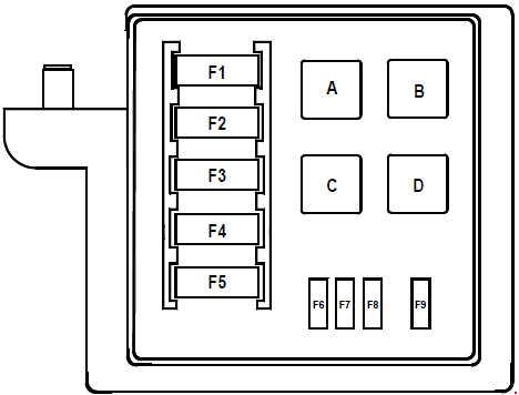
| Pozycja | Amperaż [A] | Chroniony obwód / funkcja |
|---|---|---|
| F1 | – | Unoccupied position |
| F2 | – | Unoccupied position |
| F3 | – | Unoccupied position |
| F4 | – | Unoccupied position |
| F5 | 60 | 60 A radiator cooling fan high-speed feed through its relay |
| F6 | 20 | 20 A additional fuel pump feed on K4M864 and M4R752/M4R753 engines, where equipped |
| F7 | – | Unoccupied position |
| F8 | 30 | 30 A radiator cooling fan low-speed feed through resistor and UPC switching controls |
| F9 | – | Unoccupied position |
| A | – | Relay A – unoccupied in this original carrier |
| B | 20 | Relay B – 20 A additional fuel pump relay on K4M864 and M4R752/M4R753 engine variants |
| C | 20 | Relay C – 20 A reversing light relay on automatic transmission versions |
| D | – | Relay D – unoccupied in this original carrier |
Battery main protection block – F1-F7 and auxiliary slots
Here F1 has two incompatible alternatives: 300 A on M4R714/M4R751/M4R752/M4R753 and 190 A on K4M838/K4M864/F4R872. These are alternative protection ratings for the same fuse position, determined by engine installation, not two separate F1 slots. F4 (300 A on the specified M4R variants) distributes alternator and engine fuse power; the archived table does not establish the F4 current for the K4M/F4R arrangement, so it remains “-“.
F5 (80 A) supplies electric power steering, F6 (35 A) the UPC and F7 (5 A) its control supply. F2/F3 distribute power to sets of cabin fuses. Positions 2 and 3 in the separate minor group are unoccupied and have been retained.
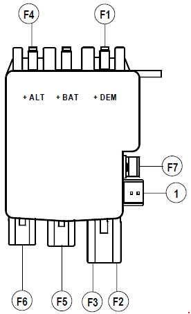
| Pozycja | Amperaż [A] | Chroniony obwód / funkcja |
|---|---|---|
| F1 | 300 | F1 300 A starter/battery main protection on M4R714/M4R751/M4R752/M4R753 engines |
| F1 | 190 | F1 190 A alternative starter/battery protection on K4M838/K4M864/F4R872 engines; same physical position, different engine type |
| F2 | 50 | F2 50 A power supply to cabin fuses F30-F36 |
| F3 | 80 | F3 80 A power supply to cabin fuses F10, F26 and F27, and UPC module |
| F4 | 300 | F4 300 A alternator and engine fuse carrier main power on M4R714/M4R751/M4R752/M4R753 |
| F4 | – | F4 alternator and main fuse carrier supply on K4M838/K4M864/F4R872; original table does not confirm the amp rating |
| F5 | 80 | F5 80 A electric power steering main supply |
| F6 | 35 | F6 35 A UPC protection/switching module power |
| F7 | 5 | F7 5 A UPC module control power |
| 1 | 5 | 5 A protected permanent battery-positive input to UPC |
| 2 | – | Unoccupied position |
| 3 | – | Unoccupied position |
Dedicated radiator cooling fan fuse 234 – 70 A
The separate protection labelled 234 (70 A) is fitted beside the engine radiator cooling fan assembly. It is distinct from the 60 A high-speed and 30 A low-speed fuses in the engine auxiliary unit, and entirely unrelated to the cabin HVAC blower F40. The original image is small and should be treated as a position reference rather than a scalable circuit drawing.

| Pozycja | Amperaż [A] | Chroniony obwód / funkcja |
|---|---|---|
| 234 | 70 | Special protection position 234 – 70 A engine radiator cooling fan assembly main supply; separate physical unit beside the cooling fan |
Key-card, engine, gearbox and equipment differences
Key-card versus conventional key: the UCH/UPC systems use different ignition and steering-column lock supplies. The cabin second-row accessory socket F4 and some blower switching apply particularly to key-card installations. Engine family: the 190/300 A starting protection changes with specific K4M, F4R and M4R engine codes, and the additional fuel-pump circuit is fitted only to particular M4R752/M4R753 and K4M864 versions.
Automatic transmission: the engine UPC fuses 12/15 and supplementary reverse-light relay C differ from a manual gearbox. Electronic parking brake: its separate control and safety circuits must not be assumed to correspond to an unrelated open slot in these seven diagrams. An electronic parking brake warning requires model-specific diagnosis.
This Grand Scenic II is not the earlier Renault Scenic I (1996-2003). For another Renault electrical system of the era, see Renault Espace IV. Do not copy fuse positions between these different UPC/UCH installations.
Common Grand Scenic II electrical fault checks
Front 12 V lighter dead: inspect cabin F3 (10 A); on key-card models the second-row accessory supply can use F4 (10 A). Heater blower does not work: check cabin F40 (40 A) and the additional blower relay C (70 A) where fitted, then diagnose the blower resistor/motor. Do not use the 70 A engine fan fuse for this symptom.
Rear window not heating: check cabin F42 (40 A), the cabin carrier’s C 40 A relay, tailgate contacts and glass heating elements. All stop lamps out: inspect cabin F37 (10 A) and the related brake switch signal F15 (5 A), then the pedal switch and UCH connections.
Engine radiator fan fails at low speed: inspect the separate F8 (30 A), resistor and fan control; for high speed, F5 (60 A), its relay and the dedicated 234 (70 A) main feed may be involved. Electric power steering warning: check battery voltage and earth connections, then the main F5 (80 A) battery-area fuse and engine UPC position 16 (5 A).
Starter issues on a petrol car: before checking the main 190/300 A link, confirm the exact engine code, battery and immobiliser state. Automatic gearbox reversing lamps fail: compare UPC position 17 (10 A) and auxiliary relay C 20 A; a manual gearbox uses a different reverse switch control.