
Skoda Citigo (2014) has a 51-position main fuse carrier beneath the steering wheel, additional fuses beside the battery and a separate 12-position panel at the side of the dashboard on models with the Start-Stop system. Engine, automated manual gearbox ASG, market and build date can alter occupancy and current ratings. The electric Citigo-e iV has a different high-voltage installation and is outside this 2014 petrol model guide.
The guide contains all 82 fuse and equipment entries from the Polish article, in four complete tables: 51 main dashboard positions, 13 SA/SB battery-area high-current positions, six engine-bay owner-manual entries S1-S6 and twelve supplementary Start-Stop positions SD1-SD12. The three original model-specific fuse drawings remain. All amp ratings must be checked against the installed fuse card before replacing a high-current link.
Where are the fuses in a 2014 Skoda Citigo?
Main passenger compartment panel SC: switch off the ignition and electrical consumers. Move the driver’s seat back and locate the fuse holder on the underside of the dashboard directly below the steering wheel. Press its securing tab, move the cover in the direction marked by the arrow and use the built-in puller to inspect the correct numbered fuse. Refit the clip and close the cover until it locks. This is not the side-panel SD carrier found on cars with Start-Stop.
Engine-bay fuse protection: open the bonnet and locate the covered distribution housing beside the battery. Press both retaining tabs to access the six-position S1-S6 group. The adjacent large bolted SA/SB battery-feed strip requires specialist precautions and should not be unplugged or shorted while the battery is connected.
Supplementary Start-Stop panel SD: where fitted, open the driver’s door and carefully remove the small side cover at the left end of the dashboard. This panel is separate from the underside SC carrier and contains SD1-SD12. On right-hand-drive vehicles the trim access may be different.
Main fuse panel below the steering wheel – SC1-SC51
The 2014 owner’s manual assigns SC36 to the cigarette lighter and 12 V socket, SC37 to the blower, SC41 to central locking, SC46 to the heated rear window and SC49 to the front windscreen wipers. The ratings shown below are sourced from the specific archived 2014 fuse card. SC35 is a fuel-pump assignment in the May 2014 owner’s manual but can be vacant in other charts; no unconfirmed amperage is invented.
SC26 caution: the factory May 2014 owner’s manual marks position 26 as not assigned, while an older auxiliary equipment list identifies a main relay/instrument function there. The table notes both rather than representing one as universal. SC50 has alternative 15/20 A equipment versions, so its amperage must come from the fuse card inside the actual car.
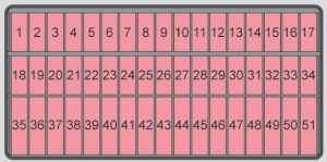
| Pozycja | Amperaż [A] | Chroniony obwód / funkcja |
|---|---|---|
| SC1 | 7.5 | Telephone, radiator fan, instrument cluster and engine ECU |
| SC2 | 15 | OBD diagnostic connector, air-conditioning relay and controller, refrigerant pressure sensor |
| SC3 | 7.5 | Clutch pedal and brake pedal switches |
| SC4 | 7.5 | Switch backlighting, number plate illumination and lighting controller on equipped versions |
| SC5 | 7.5 | Steering column switch and central body electronics control unit |
| SC6 | 7.5 | Headlamp range adjustment and exterior mirror adjustment |
| SC7 | 10 | ASG automated transmission selector, if fitted |
| SC8 | 7.5 | ASG automated transmission controller and selector, if fitted |
| SC9 | 7.5 | Airbag controller and dashboard switch panel |
| SC10 | 7.5 | Parking assistance system, where equipped |
| SC11 | 10 | Right dipped-beam headlamp |
| SC12 | 7.5 | Rear fog lamp and instrument cluster |
| SC13 | 10 | Left dipped-beam headlamp |
| SC14 | 15 | Rear-window wiper motor |
| SC15 | 15 | Exterior light switch |
| SC16 | 7.5 | Electric power steering control signal |
| SC17 | 15 | Windscreen washer pumps |
| SC18 | 7.5 | Reversing light switch |
| SC19 | 15 | Fuel injection valves and coolant pump |
| SC20 | 7.5 | ABS and ESP control module |
| SC21 | 7.5 | Right parking/position lights and number plate lighting |
| SC22 | 10 | Daytime running lamps |
| SC23 | 7.5 | Left parking and position lights |
| SC24 | 15 | Headlamp flash / high-beam flash switch |
| SC25 | 10 | Windscreen washer controls |
| SC26 | 7.5 | Not assigned in the May 2014 factory owner’s manual; an archived equipment list mentions the main relay and instrument cluster |
| SC27 | 7.5 | Passenger compartment courtesy lights |
| SC28 | 7.5 | Diagnostic connector |
| SC29 | 7.5 | Central electrical system control module |
| SC30 | 7.5 | Heated exterior mirrors |
| SC31 | 10 | Cooling fan and lambda/oxygen sensor |
| SC32 | 15 | Direction indicators, stop lamps, body control module and daytime running lamps, version-dependent |
| SC33 | 10 | Right high-beam headlamp |
| SC34 | 10 | Left high-beam headlamp and high-beam indicator |
| SC35 | – | Fuel pump in the May 2014 factory manual; fuse rating not confirmed for the archived configuration, and unused on some equipment lists |
| SC36 | 20 | Cigarette lighter and 12 V accessory outlet |
| SC37 | 30 | Fresh-air heater/air-conditioning blower motor |
| SC38 | 15 | Radio and audio system |
| SC39 | 30 | Panoramic sliding roof and horn |
| SC40 | 15 | Engine electronic control module |
| SC41 | 25 | Central door locking system |
| SC42 | 25 | Ignition modules / ignition coils |
| SC43 | 20 | Front seat heaters, where equipped |
| SC44 | 15 | Fuel pump supply |
| SC45 | 20 | Main light switch |
| SC46 | 30 | Heated rear-window demister |
| SC47 | 30 | Right electric window, or door control on some right-hand-drive versions |
| SC48 | 20 | Horn |
| SC49 | 30 | Front windscreen wiper motor and related controls |
| SC50 | 15/20 | Front fog lamps in 15 A layout, or body control electronics in a 20 A Start-Stop-related layout; confirm installed fuse rating |
| SC51 | 30 | Left electric window or driver-door controller, later equipment dependent |
Additional high-current fuse carrier – SA1-SA7 and SB1-SB6
The battery-related power carrier protects the alternator, ABS, power steering, cooling and ASG automated transmission controller, with additional lower-current body/ignition circuits. The source uses an SA1-SA7 designation running from the alternator side; some external component diagrams enumerate the same seven electrical functions in the reverse direction. Do not treat the archive’s SA index as a physical slot location until the stamped carrier markings are confirmed. Ratings of the 150/175 A alternator link depend particularly on factory Start-Stop.
No additional high-resolution, identical 2014 SA/SB location drawing has been verified for this source. The functional table is complete, but precise high-current slot positions must be read from the installed distribution strip or vehicle-specific service wiring diagram.
| Pozycja | Amperaż [A] | Chroniony obwód / funkcja |
|---|---|---|
| SA1 | 150/175 | Alternator main fusible link: 150 A without Start-Stop or 175 A with factory Start-Stop in the archived SA1 naming scheme |
| SA2 | 30 | Optional factory audio amplifier main power, absent on some vehicles |
| SA3 | 110 | Main supply to the under-dashboard carrier and electrical load/main supply relays |
| SA4 | 50 | Electric power steering main current feed |
| SA5 | 40 | ABS/ESP hydraulic controller main supply |
| SA6 | 40 | Engine radiator cooling fan controller |
| SA7 | 50 | Automated manual transmission ASG controller, if installed |
| SB1 | 30 | Additional ABS/ESP controller power |
| SB2 | 30 | Radiator fan thermal switching circuit |
| SB3 | 7.5 | Radiator fan controller and ignition terminal feed |
| SB4 | 10 | Additional ABS/ESP electronic control supply |
| SB5 | 7.5 | Body electrical system control unit, equipment dependent |
| SB6 | 30 | Ignition switch and passenger power distribution supply |
Owner-manual engine compartment fuse panel – S1-S6
The owner’s handbook separately identifies six engine-bay functions: ABS/ESP, radiator cooling fan, cooling controller/ignition, central electronics/battery management and starter/ignition lock. The handbook does not give a complete set of currents next to this six-position list, so the table deliberately leaves the amperage field as “-” instead of importing an unrelated SA/SB number.
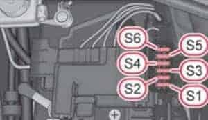
| Pozycja | Amperaż [A] | Chroniony obwód / funkcja |
|---|---|---|
| S1 | – | ABS and ESP |
| S2 | – | Engine cooling/radiator fan |
| S3 | – | Radiator fan controller and ignition |
| S4 | – | ABS and ESP |
| S5 | – | Central body control unit and battery management electronics |
| S6 | – | Ignition lock and starter |
Start-Stop supplementary dashboard panel – SD1-SD12
Citigo cars with Start-Stop have another panel for ABS/ESP, instruments, radio/diagnostics, DC-DC converter, starter and headlamp circuits. Positions SD5-SD8 are unused on the 2014 factory chart. Fuse values for this particular supplementary holder are not specified by the original owner manual list; do not transfer amperage values from a same-numbered SC position.
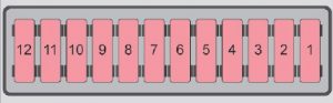
| Pozycja | Amperaż [A] | Chroniony obwód / funkcja |
|---|---|---|
| SD1 | – | ABS and ESP controls |
| SD2 | – | Instrument cluster |
| SD3 | – | Radio and onboard diagnostic connector |
| SD4 | – | DC-DC voltage converter, starter relay and switch panel |
| SD5 | – | Unoccupied in the May 2014 manual |
| SD6 | – | Unoccupied in the May 2014 manual |
| SD7 | – | Unoccupied in the May 2014 manual |
| SD8 | – | Unoccupied in the May 2014 manual |
| SD9 | – | Headlamp circuit |
| SD10 | – | Headlamp circuit |
| SD11 | – | Starter circuit |
| SD12 | – | DC-DC voltage converter, ABS, instrument cluster and radio |
2014 build changes, gearbox and Start-Stop equipment
The Citigo 1.0 MPI came with conventional and Start-Stop equipment and, optionally, the ASG automated transmission. ASG-specific protections may be absent on a manual car. From around November 2014, some service fuse cards list different power-window and door-control wiring. Confirm whether the physical carrier is the pre- or post-change version before using another 2014 chart.
The 2012 Skoda Citigo fuse diagram documents an earlier build, and the related 2013 SEAT Mii fuse guide has a similar platform. Neither substitutes for the original fuse card of a 2014 Citigo with different Start-Stop equipment.
Useful electrical fault checks on Citigo
Cigarette lighter has no power: inspect SC36 (20 A), the socket contacts and any connected charger. Cabin fan stopped: check SC37 (30 A), then the blower regulator and motor. Central locking fails: check SC41 (25 A) along with the door wiring and actuators.
Rear wiper stopped: inspect SC14 (15 A) and the wiring where the tailgate flexes. Front windscreen wipers not moving: verify SC49 (30 A) and the wiper linkage. Rear screen demister fails: inspect SC46 (30 A), glass terminals and the heating grid.
Start-Stop warning or difficult restart: check the supplementary SD4 and SD12 converter/starter circuits and battery state, but compare the fuse ratings with the actual Start-Stop holder. Electric power steering warning: inspect low-current steering supply SC16 and the appropriate battery-area main power feed, then scan the steering controller for codes rather than replacing the large fuse on suspicion alone.