
Skoda Superb II 3T (2008-2015) is the second generation of Skoda’s large family car, available as a TwinDoor liftback and Superb Combi estate. Popular engines include the 1.9 TDI and 2.0 TDI diesels, alongside 1.4 TSI, 1.8 TSI, 2.0 TSI and 3.6 FSI V6 petrol units. Manual or DSG transmissions, Haldex 4×4 and KESSY keyless entry can affect the fuse assignments.
Fuse boxes are located in the left end of the dashboard and near the battery in the engine compartment. The engine compartment has two distinct variants: type A with 54 numbered locations F1-F54 and type B with 30 locations F1-F30. They must not be used interchangeably. This guide compares manufacturer documentation from 2008, 2011 and 2012, retaining spare positions and engine-specific differences. Where the 2012 handbook identifies a function without a fuse rating, the amperage is deliberately left unspecified rather than guessed.
Where are the Skoda Superb II fuse boxes?
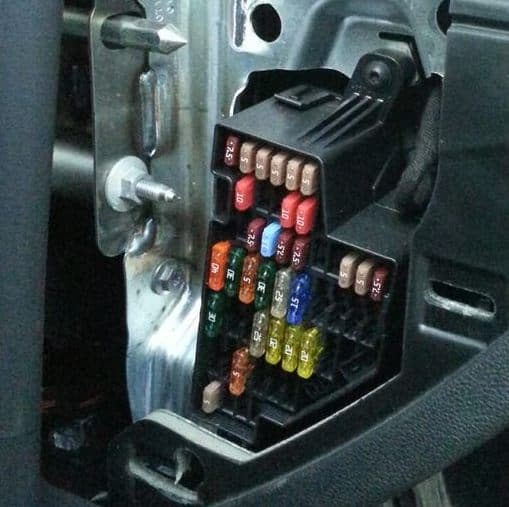
Passenger compartment: on a left-hand-drive car, open the driver’s door and look at the exposed end of the dashboard near the driver’s knee. Switch off the ignition and all electrical equipment. Gently prise off the end cover using a plastic trim tool or a protected flat tool, taking care of the clips. Behind it is the 49-position panel. Use a plastic fuse puller to remove a blown blade fuse and only replace it with the original rating.
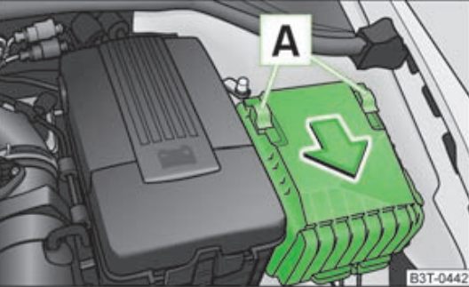
Engine compartment: open the bonnet and find the black fuse box next to the battery on the left side of the engine bay when facing forward. Depending on the car, access may involve removing part of the battery cover. Release the lid’s two retaining clips and lift it off. Refit and secure them fully to prevent water and corrosion. Determine whether the fitted box is type A or B by its physical layout and the numbered diagram.
Some cars also have bolt-mounted main battery links. The cited handbooks do not specify one universal rating for every such link. Do not replace these high-current components without VIN-specific technical information and appropriate isolation procedures.
Passenger compartment – positions 1-49
The physical numbering covers 49 slots, but assignments differ between 2008-2015 and optional equipment. Distinct entries preserve changes to positions 12, 17-21, 25, 28-31, 39, 41 and 46-48. Multiple rows for the same position represent different versions and are not fuses that should be installed together.
Front and rear cigarette lighters and console 12 V sockets: position 35 (25 A). The boot 12 V outlet uses position 26 (25 A). KESSY, powered tailgate, heated seats and trailer wiring introduce additional circuits on suitably equipped vehicles.
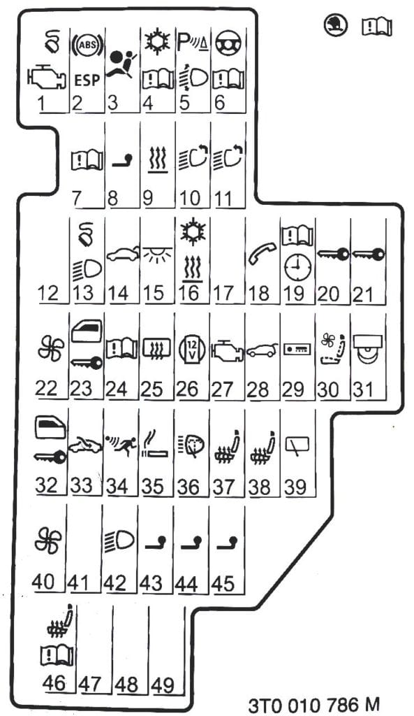
| Position | Amperage [A] | Protected circuit / function |
|---|---|---|
| 1 | 7.5 | 2008-2011: OBD socket, engine ECU power supply, relay and fuel pump controller |
| 2 | 5 | ABS/ESP controller, brake sensor and tyre pressure monitoring |
| 3 | 5 | Airbag ECU and front passenger airbag deactivation switch |
| 4 | 5 | Service interval system, rear lights, auto-dimming mirror and telephone |
| 5 | 5 | Headlamp adjustment and levelling, parking sensors and Park Assist |
| 6 | 5 | Instruments, electromechanical steering, Haldex 4×4 controller and selector lock |
| 7 | 10 | Crankcase ventilation heating and mass air flow sensor |
| 8 | 5 | Factory trailer wiring module |
| 9 | 5 | Parking heater and ventilation relay |
| 10 | 10 | Left adaptive headlamp, if fitted |
| 11 | 10 | Right adaptive headlamp, if fitted |
| 12 | 10 | 2008-2009: front door central locking |
| 12 | – | 2011-2015: unoccupied according to the applicable handbook |
| 13 | 7.5 | OBD diagnostic socket, light switch, rain sensor and clock |
| 14 | 15 | Central locking and bonnet-open sensor |
| 15 | 7.5 | Interior lighting central control unit |
| 16 | 7.5 | Air-conditioning controller |
| 17 | 10 | 2008-2009: rear door central locking |
| 17 | – | 2011-2015: unused position |
| 18 | – | 2008-2011: unused in the corresponding main fuse listing |
| 18 | – | 2012-2015: factory telephone module; rating not supplied in that handbook |
| 19 | – | 2008-2011: unoccupied |
| 19 | – | 2012-2015: instrument cluster and wiper/indicator stalk; amperage not confirmed |
| 20 | 5 | 2008-2009: ABS/ESP and hill-hold assistance |
| 20 | 5 | 2011 onwards: KESSY keyless entry and start |
| 21 | – | 2008-2009: unoccupied |
| 21 | 7.5 | 2011 onwards: KESSY electronic steering lock |
| 22 | 40 | Climatronic cabin blower |
| 23 | 30 | Front electric windows and front door central locking |
| 24 | 5 | Automatic gearbox selector lever interlock |
| 25 | 25 | 2008-2009: heated rear window |
| 25 | 30 | 2008-2015: auxiliary heater and heated rear-window relay configuration |
| 26 | 25 | Luggage compartment 12 V socket |
| 27 | 15 | Fuel pump relay, 15 A variant |
| 27 | 20 | Fuel pump relay, fuel pump controller and injectors, 20 A variant |
| 28 | – | 2008-2009: no assigned function |
| 28 | 30 | 2011 onwards: powered boot lid, if fitted |
| 29 | – | 2008-2009: no assigned function |
| 29 | 5 | 2011: preparation for a non-factory radio |
| 29 | – | 2012-2015: automatic transmission and Haldex clutch controller; rating not supplied |
| 30 | – | 2008-2011: no assigned function |
| 30 | – | 2012-2015: front seat ventilation; rating not specified |
| 31 | – | 2008-2011: no assigned function |
| 31 | – | 2012-2015: DVD wiring preparation; rating not specified |
| 32 | 30 | Rear electric windows and rear door central locking |
| 33 | 25 | Electric sunroof, if fitted |
| 34 | 5 | Alarm siren and security system |
| 35 | 25 | Front and rear cigarette lighters and console 12 V sockets |
| 36 | 20 | Headlamp washers |
| 37 | 20 | Heated front seats |
| 38 | 20 | Heated rear seats, if fitted |
| 39 | – | 2008-2011: no assigned function |
| 39 | – | 2012-2015: rear wiper on Combi estate; rating not listed in 2012 handbook |
| 40 | 40 | Air-conditioning blower and parking heater relay |
| 41 | 10 | 2011: rear wiper, if fitted |
| 41 | – | 2008-2009 and 2012-2015: unused according to the model-year listing |
| 42 | 5 | Lighting switch |
| 43 | 15 | Trailer recognition controller, circuit one |
| 44 | 20 | Trailer controller, circuit two |
| 45 | 15 | Trailer controller, circuit three |
| 46 | 5 | 2008-2011: heated washer jets, parking heater relay and seat heating |
| 46 | – | 2012-2015: heated seat switch; rating not supplied |
| 47 | – | 2008-2011: no assigned function |
| 47 | – | 2012-2015: factory phone preparation; rating not supplied |
| 48 | – | 2008-2011: no assigned function |
| 48 | – | 2012-2015: aftermarket radio preparation; rating not supplied |
| 49 | – | 2008-2015: unoccupied in basic handbook listings |
| 49 | – | Some Start-Stop electrical versions may have extra electronics connected |
Under-bonnet fuse box type A – F1-F54
The type A module contains 54 numbered fuse locations, including unused and reserve sockets. In earlier layouts, F31 (30 A) protects the front wipers, F48 (40 A) the ABS pump, and F47 (30 A) the left front and rear lamps. The 2012 manufacturer’s listing differs at positions including F6, F9, F11, F12, F39-F42 and F49, with alternative rows retained.
A dash in the amperage column alongside a named 2012 circuit means that the cited manual does not give a rating. It does not mean the circuit operates without a fuse or is necessarily empty.
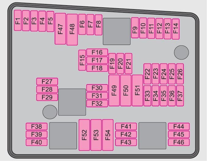
| Position | Amperage [A] | Protected circuit / function |
|---|---|---|
| F1 | 30 | Right headlamp and right rear light |
| F2 | 20 | ABS/ESP control valves |
| F3 | – | Spare position |
| F4 | – | Spare position |
| F5 | 15 | Horn |
| F6 | 40 | 2008-2009: ignition-switched terminal 15 supply |
| F6 | – | 2011-2015: unoccupied in corresponding layout |
| F7 | – | Unoccupied |
| F8 | – | Unoccupied |
| F9 | 10 | 2008-2011: auxiliary engine-control valves |
| F9 | – | 2012-2015: unoccupied in manufacturer listing |
| F10 | – | Unoccupied |
| F11 | 10 | 2008-2011: oxygen sensor |
| F11 | – | 2012-2015: unoccupied in manufacturer listing |
| F12 | 10 | 2008-2011: second oxygen sensor circuit |
| F12 | – | 2012-2015: unoccupied |
| F13 | 15 | Automatic transmission controller |
| F14 | – | Unoccupied |
| F15 | 10 | Coolant circulation pump |
| F16 | – | Unoccupied |
| F17 | 5 | Instrument cluster and wiper/indicator switch |
| F18 | 30 | Audio system amplifier |
| F19 | 15 | Radio |
| F20 | 5 | 2008-2011: factory telephone |
| F20 | – | 2012-2015: unoccupied in manufacturer listing |
| F21 | – | Unoccupied |
| F22 | – | Unoccupied |
| F23 | 10 | Engine control ECU |
| F24 | 5 | CAN bus communication controller |
| F25 | – | Unoccupied |
| F26 | – | Unoccupied |
| F27 | 15 | Fuel metering valve |
| F28 | 15 | Engine ECU, 15 A variant |
| F28 | 25 | 2011: engine ECU, 25 A variant |
| F29 | 5 | Main relay |
| F30 | 20 | Parking heater and ventilation controller |
| F31 | 30 | Front windscreen wiper motor |
| F32 | – | Unoccupied |
| F33 | – | Unoccupied |
| F34 | – | Unoccupied |
| F35 | – | Unoccupied |
| F36 | – | Unoccupied |
| F37 | – | Unoccupied |
| F38 | 10 | Cooling fan and control valves |
| F39 | – | 2008-2011: unoccupied |
| F39 | – | 2012-2015: clutch pedal and brake pad wear sensors; rating not supplied |
| F40 | – | 2008-2011: unoccupied |
| F40 | – | 2012-2015: oxygen sensor; rating not supplied |
| F41 | – | 2008-2011: unoccupied |
| F41 | – | 2012-2015: EVAP fuel vapour purge valve; rating not supplied |
| F42 | – | 2008-2011: unoccupied |
| F42 | – | 2012-2015: oxygen sensor; rating not supplied |
| F43 | 30 | Ignition power feed |
| F44 | – | Unoccupied |
| F45 | – | Unoccupied |
| F46 | – | Unoccupied |
| F47 | 30 | Left headlamp and left rear light |
| F48 | 40 | ABS/ESP pump |
| F49 | – | 2008-2009: no assigned function |
| F49 | 50 | 2011: ignition-switched terminal 15 supply |
| F49 | – | 2012-2015: terminal 15 supply; rating not supplied |
| F50 | – | Unoccupied |
| F51 | – | Unoccupied |
| F52 | 40 | Terminal X load-reduction relay |
| F53 | 50 | Additional equipment and cabin fuse panel supply |
| F54 | – | Unoccupied |
Under-bonnet fuse box type B – F1-F30
The type B unit has a different physical layout and just 30 numbered fuse locations. Here F19 (30 A) is for the front wipers, F17 (15 A) the horn, F25 (30 or 40 A) the ABS pump, and F27 (40 or 50 A) the diesel glow-plug controller. DSG versions use distinct F2 and F5 circuits. Petrol and diesel assignments differ at F15 and F20; the table also preserves changes between the 2008, 2011 and 2012 handbook editions.
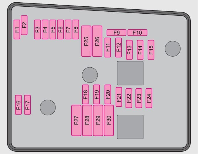
| Position | Amperage [A] | Protected circuit / function |
|---|---|---|
| F1 | – | Unoccupied |
| F2 | 30 | DSG DQ200 dual-clutch gearbox controller |
| F3 | 5 | Measurement circuit |
| F4 | 20 | ABS valve circuit, 20 A variant |
| F4 | 30 | ABS valve circuit, 30 A variant |
| F5 | 15 | DSG DQ250 dual-clutch gearbox controller |
| F6 | 5 | 2008-2011: instruments, windscreen wiper and indicator switch |
| F6 | – | 2012-2015: unoccupied |
| F7 | 40 | 2008-2011: ignition-switched terminal 15 supply |
| F7 | – | 2012-2015: terminal X load-reduction relay feed; rating not supplied |
| F8 | 15 | Radio |
| F9 | 5 | 2008-2011: factory telephone |
| F9 | – | 2012-2015: unoccupied |
| F10 | 5 | Engine ECU and main relay, 5 A variant |
| F10 | 10 | Engine ECU and main relay, 10 A variant |
| F11 | 20 | Parking heater |
| F12 | 5 | CAN bus communications module |
| F13 | 15 | Engine ECU, 15 A variant |
| F13 | 20 | 2011: engine ECU, 20 A variant |
| F13 | 30 | Engine ECU, 30 A variant |
| F14 | 20 | Ignition power supply |
| F15 | 10 | Oxygen sensor on petrol engine |
| F15 | 5 | Glow-plug relay and fuel pump on diesel engine |
| F16 | 30 | Right headlamp and right rear lamp |
| F17 | 15 | Horn |
| F18 | 30 | Audio system amplifier |
| F19 | 30 | Front windscreen wipers |
| F20 | 20 | Fuel metering valve |
| F20 | 10 | Coolant circulation pump |
| F21 | 10 | Oxygen sensor, 10 A variant |
| F21 | 15 | Oxygen sensor, 15 A variant |
| F21 | 20 | 2011: oxygen sensor, 20 A variant |
| F22 | – | 2008-2009: unoccupied |
| F22 | 5 | 2011: clutch pedal position sensor |
| F22 | – | 2012-2015: clutch sensor; rating not supplied |
| F23 | 5 | Main relay, 5 A variant |
| F23 | 10 | Engine ancillary control valves, 10 A variant |
| F23 | 15 | High-pressure pump, 15 A variant |
| F24 | 10 | Radiator cooling fan |
| F25 | 30 | ABS pump, 30 A variant |
| F25 | 40 | ABS pump, 40 A variant |
| F26 | 30 | Left headlamp |
| F27 | 50 | Diesel glow-plug controller, 50 A variant |
| F27 | 40 | 2011: diesel glow-plug controller, 40 A variant |
| F28 | – | 2008: unoccupied |
| F28 | 50 | 2011: heated windscreen |
| F28 | – | 2012-2015: heated windscreen; rating not confirmed |
| F29 | 50 | Optional equipment power supply |
| F30 | 50 | Terminal X load-reduction relay, earlier variant |
| F30 | – | 2012-2015: ignition-switched terminal 15 supply; rating not supplied |
Relay positions and supplementary electrical protection
Additional relays and thermal protection for powered seats can sit behind the driver’s lower dashboard trim. The engine type A box shows four relay positions, while type B has two. Unknown or unused relay positions remain in the table without invented circuit functions. Occupancy varies with engine, gearbox and equipment.
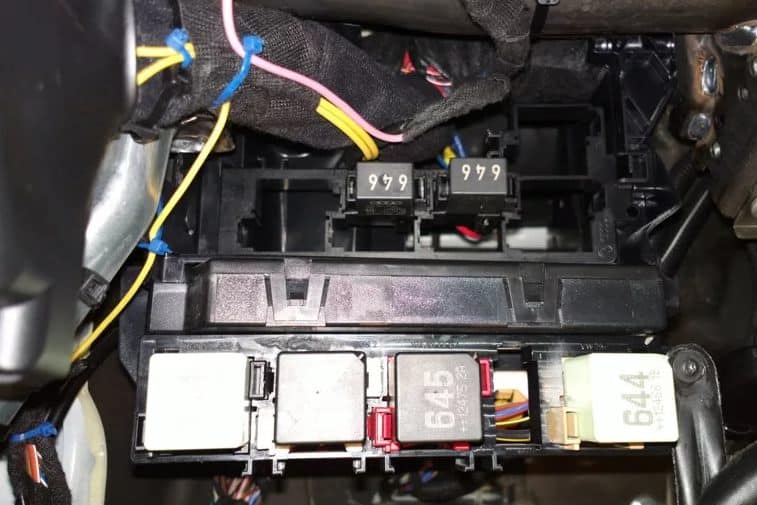
| Position | Amperage [A] | Protected circuit / function |
|---|---|---|
| A1 | – | Type A engine box relay carrier: position 1, no allocation in early table |
| A2 | – | Type A engine box relay carrier: coolant circulation pump relay |
| A3 | – | Type A engine box relay carrier: position 3, no assigned function |
| A4 | – | Type A engine box relay carrier: position 4, no assigned function |
| B1 | – | Type B engine box relay carrier: position 1, no assigned function |
| B2 | – | Type B engine box relay carrier: position 2, no assigned function |
Differences by production year and engine
2008-2009: the early manuals list ratings for many positions, including cabin 12 (10 A) for front locking, 17 (10 A) for rear locks and 20 (5 A) for ABS/ESP or hill-hold assistance. Engine type A F6 (40 A) feeds ignition terminal 15. On type B, petrol cars may use F15 (10 A) for the oxygen sensor, while some diesels use F15 (5 A) for glow-plug and fuel-related controls.
2011: KESSY keyless access, powered luggage-compartment lids and additional equipment supplies appear in some configurations. Cabin position 41 may serve the estate’s rear wiper at 10 A. Engine type A F49 can be assigned 50 A for ignition-switched supply.
2012-2015: the 2012 handbook retains the 49-position cabin numbering and both engine-box types, but does not print an amperage for every circuit. This is why some later entries have a dash. Differences also continue after the 2013 facelift, depending on engine code, DSG, KESSY, Haldex, parking heater and sales market.
Liftback versus Combi: an estate can have a rear wiper, a powered tailgate and a boot outlet that need distinct fuses. A basic liftback without those options need not have every equivalent fuse installed.
Skoda Superb II – electrical troubleshooting
Cigarette lighter or 12 V outlet is dead: check cabin position 35 (25 A) for console outlets and position 26 (25 A) for the boot socket. Disconnect any charger before replacing the fuse. Never fit 30 A in place of an original 25 A fuse.
No cabin airflow: Climatronic uses position 22 (40 A), while the blower and parking heater arrangement may also involve position 40 (40 A). If only one fan speed works, investigate the blower controller rather than raising the fuse rating.
Front wipers fail: inspect engine-box F31 (30 A) on type A, or F19 (30 A) on type B. The Combi’s rear wiper has separate protection that varies by model year. If the fuses are sound, inspect the linkage and motor wiring.
Horn is silent: engine type A uses F5 (15 A); type B uses F17 (15 A). Check the relay and horn itself if the fuse is intact.
Heated rear window does not work: cabin position 25 may be 25 or 30 A depending on the version. Partial heating can indicate damaged heating tracks or tailgate wiring.
ABS or ESP warning: type A has the main ABS pump on F48 (40 A); type B uses F25 (30 or 40 A). If the fuses are intact, read diagnostic codes and check wheel-speed sensors.
Engine will not start: relevant engine ECU, main relay and fuel pump feeds vary by engine and fuse-box type. Before replacing components, check battery voltage, terminal connections and engine earths.
Other Skoda generations and related models
The earlier model is Skoda Superb I 3U (2004-2005). The successor has its own wiring, described in Skoda Superb III 3V (2015-2016). The Skoda Octavia II 1Z (2004-2013) shares some Volkswagen Group powertrain technology, but its fuse positions are not interchangeable.
Technical references: Skoda Superb II manufacturer’s handbooks from 2008, 2011 and 2012, the “Fuses and light bulbs” sections, and the relevant relay diagrams. When a list differs from your car, the installed box, VIN and original factory documentation take precedence.
Vehicle photograph: M 93 / Wikimedia Commons, public domain.