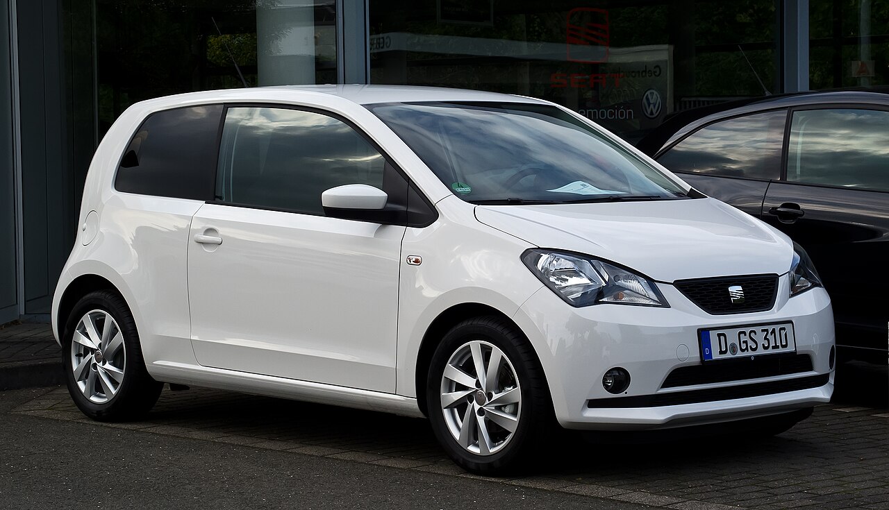
SEAT Mii (2013), type AA, has 51 standard fuse positions in its driver-side passenger-compartment carrier SC. Under the bonnet, the battery-area carrier is divided into seven high-current SA positions and six SB positions. Cars with the factory Start-Stop system also use a separately numbered SD panel with 12 positions.
May 2013 is an important changeover. Several SC, SA, SB and SD ratings differ between earlier cars and those built from May 2013. The tables retain all 76 positions, unused slots and optional ASG, heated seat, parking sensor and Start-Stop circuits. An amperage shown as 5/7.5 or 40/50 means two different factory configurations, never permission to choose the larger fuse.
Where are the SEAT Mii 2013 fuse boxes?
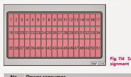
SC passenger compartment: turn off the ignition, lights and electrical accessories, open the driver’s door and locate the service flap beneath the steering wheel. Release its clip and fold the cover down. Find the physical slot using the numbered SC1-SC51 layout below. Use a plastic fuse puller and close the cover until it latches.
SA and SB at the battery: open the bonnet and locate the protected power distribution near the battery. Press the cover retaining tabs. SA is a multi-element high-current fuse strip: the manufacturer calls for replacing the specified assembly rather than breaking out one link. Inspection and replacement of these large fuses should be undertaken by a qualified workshop. The adjacent SB section is a separate, smaller fuse holder.
SD on Start-Stop cars: an additional fuse panel sits behind the left dashboard side cover on suitably equipped vehicles. Its SD1-SD12 positions are distinct from SC1-SC12, even though both are in the cabin. Right-hand-drive versions can differ in access details.
Main interior fuse carrier – SC1-SC51
This is the original 51-position SC layout for the Mii, with three bands of numbered slots. Some legends printed with older diagrams predate the May 2013 electrical update; the following table combines the two service documentation periods and must be matched to the car’s build date. SC35 is unoccupied in the documented arrangements.
| Pozycja | Amperaż [A] | Chroniony obwód / funkcja |
|---|---|---|
| 1 | 5/7.5 | Instrument cluster, engine controller and radiator fan control unit |
| 2 | 15 | Air conditioning control unit, compressor, refrigerant high-pressure sender and diagnostic socket |
| 3 | 7.5 | Clutch pedal switch, stop-lamp switch and camshaft timing control valve |
| 4 | 7.5 | On-board supply module J519, dipped beam, daytime running and high-beam switching |
| 5 | 5/7.5 | Body supply module, ignition switch and cruise control |
| 6 | 5/7.5 | Headlamp levelling and electric exterior mirror adjustment |
| 7 | 10 | Automated manual gearbox (ASG) selector, if fitted |
| 8 | 7.5 | ASG transmission controller and gear selector |
| 9 | 7.5 | Airbag control module (SRS) and centre-console switches |
| 10 | 5/7.5 | Parking assistance controller |
| 11 | 10 | Right dipped-beam headlamp |
| 12 | 5/7.5 | Rear fog light and instrument cluster |
| 13 | 10 | Left dipped-beam headlamp |
| 14 | 15 | Rear window wiper |
| 15 | 15 | Main lighting switch |
| 16 | 5/7.5 | Electric power steering controller and ignition-switched supply relay |
| 17 | 15 | Windscreen washer control switch, equipment-dependent |
| 18 | 7.5 | Reversing lamp switch |
| 19 | 15 | Fuel injectors for cylinders 1-3 |
| 20 | 5/7.5 | ABS controller and steering angle / emergency braking sensor |
| 21 | 5/7.5 | Right side and rear parking lamps, registration lamp and body controller |
| 22 | 10 | Left and right daytime running lights |
| 23 | 5/7.5 | Left side and rear parking lamps |
| 24 | 15 | Headlamp main-beam flash switch |
| 25 | 10 | Front and rear screen washer pump |
| 26 | 5/7.5 | Main relay, instrument cluster and steering angle sensor |
| 27 | 7.5 | Interior and reading lamps |
| 28 | 5/7.5 | OBD diagnostic connector |
| 29 | 7.5 | On-board supply control unit J519 |
| 30 | 5/7.5 | Heated exterior mirrors |
| 31 | 10 | Lambda oxygen sensor and EVAP purge valve |
| 32 | 15 | Body control module, indicators and brake lights |
| 33 | 10 | Right high-beam headlamp |
| 34 | 10 | Left high-beam headlamp and instrument cluster |
| 35 | – | Unused position on the documented fuse board |
| 36 | 15/20 | 12 V accessory / cigarette-lighter socket |
| 37 | 30 | Heating and air conditioning controller and blower |
| 38 | 15 | Radio |
| 39 | 30 | Panoramic sliding roof controller, if fitted |
| 40 | 15 | Engine control unit (ECU) |
| 41 | 25 | Central locking and body electronics controller |
| 42 | 25 | Ignition coils for cylinders 1-3 |
| 43 | 20 | Front heated seats and switches |
| 44 | 15 | Fuel pump relay circuit |
| 45 | 20 | Main lighting switch |
| 46 | 30 | Heated rear window |
| 47 | 25/30 | Right front power window; driver-door wiring differs on RHD cars |
| 48 | 20 | Horn and body control module |
| 49 | 20/30 | Front wiper motor and its controller |
| 50 | 15/20 | Front fog lamps; also BCM supply with Start-Stop on some cars |
| 51 | 25/30 | Left front power window and driver-door locking control |
Battery-mounted main fuses – SA1-SA7
The high-current strip distributes alternator, cabin junction, electric steering, ABS, radiator fan and automated gearbox power. SA2 may supply an optional amplifier in later configurations. This table lists the SA fuse numbers and functions, not a physical layout drawing, because the supplied article has no separate original SA diagram.
| Pozycja | Amperaż [A] | Chroniony obwód / funkcja |
|---|---|---|
| SA1 | 150/175 | Alternator: 150 A without Start-Stop or 175 A with Start-Stop, depending on installation |
| SA2 | -/30 | Optional amplifier: may be unused before May 2013; 30 A in later fitted installations |
| SA3 | 110 | Main feed to SC passenger fuses, engine main relay and load-reduction relay |
| SA4 | 40/50 | Electric power steering: 40 A early configuration or 50 A from May 2013 |
| SA5 | 40 | Anti-lock braking controller (ABS) |
| SA6 | 40 | Radiator cooling fan controller |
| SA7 | 50 | Automated manual gearbox, if equipped |
Engine compartment fuses – SB1-SB6
SB is an adjacent but separately numbered fuse carrier. SB1 is 25 A in the earlier documented system and 30 A from May 2013. SB3 similarly changes from 5 A to 7.5 A on the newer card. Verify the exact vehicle version and use only its specified fuse rating.
| Pozycja | Amperaż [A] | Chroniony obwód / funkcja |
|---|---|---|
| SB1 | 25/30 | ABS control unit: 25 A on earlier fuse cards and 30 A from May 2013 |
| SB2 | 30 | Radiator fan thermal switch and radiator fan controller |
| SB3 | 5/7.5 | Radiator fan and ignition switch feed: 5 A early or 7.5 A from May 2013 |
| SB4 | 10 | Second ABS controller supply |
| SB5 | 5 | On-board supply controller J519 |
| SB6 | 30 | Cabin fuse carrier supply and ignition switch |
Additional Start-Stop fuse holder – SD1-SD12
The Start-Stop fuse panel protects DC-DC voltage conversion, starter relays, radio and selected lighting controls. SD5-SD8 remain unused. SD1, SD2 and SD3 have different early and later ratings, so this holder must not be confused with the main SC panel.
| Pozycja | Amperaż [A] | Chroniony obwód / funkcja |
|---|---|---|
| SD1 | 5/7.5 | Emergency braking sensor and relay: 5 A early, 7.5 A from May 2013 |
| SD2 | 5/7.5 | Instrument cluster: 5 A early, 7.5 A from May 2013 |
| SD3 | 10/15 | Radio: 10 A earlier configuration, 15 A from May 2013 |
| SD4 | 7.5 | DC-DC converter and starter relays |
| SD5 | – | Unused position |
| SD6 | – | Unused position |
| SD7 | – | Unused position |
| SD8 | – | Unused position |
| SD9 | 15 | Right dipped beam, main beam and daytime lighting via J519 |
| SD10 | 15 | Left dipped beam, main beam and daytime lighting via J519 |
| SD11 | 30 | Two starter relays |
| SD12 | 30 | DC-DC voltage converter |
SEAT Mii changes before and from May 2013
Earlier than May 2013: examples include SC1 5 A, SC36 15 A, SC47 25 A, SC49 20 A, SA4 40 A and SB1 25 A. From May 2013: corresponding documented configurations use SC1 7.5 A, SC36 20 A, SC47 30 A, SC49 30 A, SA4 50 A and SB1 30 A. Several other circuits, including SC5/6/10/12/16/20/21/23/26/28/30, SD1-SD3 and SB3, also vary.
Some differences depend on the transmission and trim, not solely the year. Vehicles with ASG automated gearbox, Start-Stop, panoramic roof, heated seats or parking assistance can have different occupied sockets. Match the diagram to the exact vehicle wiring and factory fuse legend.
Common SEAT Mii electrical problems
12 V socket has no power: inspect SC36, 15 A on older cars or 20 A on the revised documented card. Disconnect phone chargers and other accessories before testing for a short inside the socket.
Front windscreen wipers stopped: check SC49, 20 A or 30 A depending on the electrical version. SC14 (15 A) supplies the rear wiper. If the correct fuse is good, check the linkage and motor for excessive resistance.
Dipped headlamp failed: right lamp SC11 (10 A), left SC13 (10 A). Heated rear window failed: SC46 (30 A). Central locking problem: SC41 (25 A) and the applicable door wiring.
Starting difficulty: after checking the battery and its ground, inspect the applicable SC feed, SB6 (30 A) and, on Start-Stop models, SD11 (30 A). SA3 is a high-current 110 A main supply and should not be serviced like a blade fuse. ABS or steering fault: check SB and SA protection before diagnosing the controller, without increasing fuse amperage.
For related small-car fuse guides, see Suzuki Ignis III (2017-2018), Toyota Aygo X (2022) and Hyundai i10 AC3 (2020). Similar vehicle sizes do not mean the same fuse numbering.