
Toyota Avensis I T22/T220 (1997-2002) uses a main engine-bay fuse and relay box, a separate passenger-compartment fuse carrier and additional accessory relays. Optional daytime running lights (DRL), air conditioning and diesel auxiliary electric heating introduce other carriers. The saloon, liftback and estate can differ, as can European left-hand-drive and UK right-hand-drive installations. This is the first-generation Avensis, not the T25 or the Avensis Verso.
The eight tables preserve all 64 positions, relays and engine/equipment alternatives in the Polish source. The drawings used for the seven illustrated panels remain unchanged; no unrelated drawing has been substituted for the optional diesel heater carrier, for which a matching verified diagram is not available. Read the fuse lid or vehicle-specific owner’s manual before selecting an alternative amp rating.
Where are the Avensis T22 fuse boxes?
Under the bonnet: switch off the ignition, wait for the cooling fan to stop and open the bonnet. Find the large plastic electrical box near the battery and the inner wing. Release the retaining tabs carefully; the original diagrams identify MAIN, FAN, EFI, ALT and ABS circuits. Additional DRL and fan relays can be mounted in smaller adjacent holders. Bolted 40-100 A fuses require the correct battery-isolation procedure.
Inside the car: on a left-hand-drive Avensis T22 look under the driver’s lower dashboard, near the steering column and side of the footwell. Release the service cover without pulling on the wiring and compare the 1-17 positions with the factory label. On right-hand-drive cars, the arrangement of the integration relay, ECU, additional relays and glovebox electronics differs. The smaller auxiliary fuse and relay units are not all located within the main panel.
Main engine compartment fuse box – positions 1-18 and relays R1-R8
MAIN 50 A supplies the main headlights, while ALT 100 A distributes alternator and charging power through multiple circuits. ABS 60 A protects the anti-lock braking system. The smaller ALT-S 5 A fuse is the alternator signal feed, not the same as the bolted ALT link. Position 10 SHORT PIN is a factory electrical jumper, not a normal fuse.

| Pozycja | Amperaż [A] | Chroniony obwód / funkcja |
|---|---|---|
| 1 | 50 | MAIN – main headlamp supply and headlamp relay |
| 2 | 40 | FAN MAIN – radiator cooling fan and FAN NO.1 relay |
| 3 | 30 | FAN SUB – air conditioning condenser fan and FAN NO.2/NO.3 relays |
| 4 | 5 | ALT-S – alternator excitation and charging signal |
| 5 | 30 | H-LP CLN – headlamp washer pump and relay, if fitted |
| 6 | 15 | HAZARD – turn indicators, hazard flashers and related alarm circuitry |
| 7 | 15 | EFI – petrol engine management ECU, injection, fuel pump, sensors and control valves |
| 8 | 30 | AM2 – main ignition switch and starter switched power |
| 9 | 10 | RAD NO.1 – radio and audio system |
| 10 | – | SHORT PIN – factory electrical bridge/shunt, not a blade fuse with an amp rating |
| 11 | 15 | HEAD (LH) – left headlamp and front left position lamp |
| 12 | 10 | HORN – horn and horn relay |
| 13 | 7.5 | DOME – cabin and boot lights, remote locking, clock, diagnostics, sunroof and alarm |
| 14 | 15 | HEAD (RH) – right headlamp and high-beam indicator |
| 15 | 10 | ECU-B – immobiliser, SRS, instrument cluster, diagnostic link, ECU and rear fog lamp |
| 16 | 40 | HTR – cabin heating and air-conditioning blower feed, resistor/controller and relay |
| 17 | 100 | ALT – main alternator charging and vehicle electrical distribution, diesel heater where installed |
| 18 | 60 | ABS – anti-lock brake hydraulic pump and control unit high-current supply |
| R1 | – | MG CLT – air conditioning compressor magnetic clutch relay |
| R2 | – | FAN NO.3 – cooling fan relay 3 |
| R3 | – | FAN NO.2 – cooling fan relay 2 |
| R4 | – | EFI – fuel injection / engine ECU relay |
| R5 | – | HEAD – headlamp main relay |
| R6 | – | HORN – horn relay |
| R7 | – | STARTER – starter motor relay |
| R8 | – | FAN NO.1 – cooling fan relay 1 |
Additional daytime-running-light fuse box
Factory DRL cars have separate 10 A right and left high-beam fuses and their local DIMMER relay R1. The relay’s number refers only to this DRL holder. A car without this equipment should not have arbitrary fuses placed into similar empty sockets.
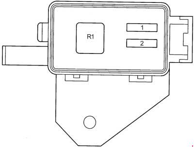
| Pozycja | Amperaż [A] | Chroniony obwód / funkcja |
|---|---|---|
| 1 | 10 | HEAD HI (RH) – right high-beam headlamp, factory daytime running light version only |
| 2 | 10 | HEAD HI (LH) – left high-beam headlamp, factory daytime running light version only |
| R1 | – | DIMMER – high/low-beam switching relay, local R1 in this separate DRL holder |
Passenger compartment fuses – 1-17 and integration relay
These circuits control the horn and lamps through supporting relays, front/rear wipers, STOP lamps, door locks, electric windows and convenience electronics. CIG & RAD position 11 (15 A) protects the cigarette lighter and radio-related accessories; WIPER position 5 (20 A) protects the wiper and washer circuits. POWER position 15 (30 A) covers factory electric windows and optionally the sunroof.
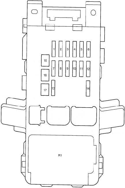
| Pozycja | Amperaż [A] | Chroniony obwód / funkcja |
|---|---|---|
| 1 | 15 | FR FOG – front fog lamps, telltale and relay, where fitted |
| 2 | 15 | SEAT HTR – optional front heated seats and switches |
| 3 | 20 | FR DEF – heated front wiper resting area and windscreen de-icer relay |
| 4 | 10 | GAUGE – instruments, ABS, air conditioning, charging, automatic transmission, sensors and ECU information |
| 5 | 20 | WIPER – front/rear wipers and washer pumps, rear wiper body-style dependent |
| 6 | 10 | IGN – ignition coils and engine management, ABS, SRS, immobiliser and gauges |
| 7 | 30 | DOOR – central locking and integration controller |
| 8 | 10 | TAIL – rear and side lamps, licence plate lamps, dash and switch illumination |
| 9 | 5 | ST – starter control, automatic neutral safety switch and ECU |
| 10 | 7.5 | TURN – indicators, dashboard telltales and hazard flasher |
| 11 | 15 | CIG & RAD – 12 V accessory/cigarette lighter socket, radio and mirror controls |
| 12 | 5 | ECU-IG – engine and ABS controllers, A/C, cooling fan relays and alarm |
| 13 | 10 | STOP – stop/brake lamps, brake switch signals to ECU and ABS |
| 14 | 5 | RR DEF I/UP – idle-speed compensation when rear-window heating is active |
| 15 | 30 | POWER – electric windows and relay, optional sunroof |
| 16 | 40 | AM1 – ignition feed to GAUGE, WIPER, TURN, ECU-IG and CIG & RAD |
| 17 | 40 | RR DEF – rear-window demister high-current supply and relay |
| R1 | – | Integration relay for multiple passenger-compartment control circuits |
Rear defogger, POWER and TAIL relays
This separate cabin relay group controls rear-window heating, electric window supply and position/tail lamps. Its R1-R3 numbering must not be confused with R1-R3 on the main engine carrier.
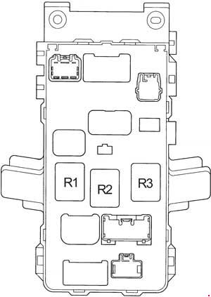
| Pozycja | Amperaż [A] | Chroniony obwód / funkcja |
|---|---|---|
| R1 | – | Rear-window defogger relay, in passenger-side relay carrier |
| R2 | – | POWER – electric window main supply relay, cabin accessory circuits |
| R3 | – | TAIL – rear and side/position lamp relay |
Auxiliary air conditioning and diesel fuel heater fuses
The small accessory carrier contains A/C 10 A for applicable air conditioning controls and FUEL HTR 30 A for the diesel fuel heater on engines fitted with it. A petrol car without fuel heating may have no fuse in the diesel-specific position.
| Pozycja | Amperaż [A] | Chroniony obwód / funkcja |
|---|---|---|
| 1 | 10 | A/C – air conditioning control switch and module, optional |
| 2 | 30 | FUEL HTR – diesel fuel heater, only when engine and equipment require it |
Rear fog light and hazard warning relays
The R1 relay serves the rear fog lamp, and local R2 operates the indicators and emergency hazard flashers. The unit is separate from the primary engine relay module.
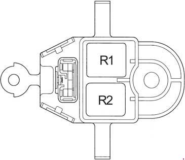
| Pozycja | Amperaż [A] | Chroniony obwód / funkcja |
|---|---|---|
| R1 | – | Rear fog lamp relay, local R1 in this supplementary carrier |
| R2 | – | Turn indicator and hazard warning flasher relay, local R2 |
Supplementary passenger heater relay
This local R1 energises the heater/ventilation blower circuit. The corresponding under-bonnet main HTR fuse is rated 40 A; a failed blower speed resistor is a separate possible cause when the fan works only on its highest speed.

| Pozycja | Amperaż [A] | Chroniony obwód / funkcja |
|---|---|---|
| R1 | – | HTR – cabin heater and ventilation blower relay, local R1 |
Optional diesel electrical auxiliary heating module
Some diesel Avensis T22 models use a separate heater assembly with three 50 A links, one 20 A ancillary supply and five relays. This installation varies with diesel engine, country and heating option, and does not exist on every T22. No model-verified physical drawing of this exact holder has been established for this article; the table is a functional reference, not a substitute for the car’s actual fuse diagram.
| Pozycja | Amperaż [A] | Chroniony obwód / funkcja |
|---|---|---|
| F1 | 50 | Diesel electric supplementary heater module / heater relay number 2 high-current supply |
| F2 | 50 | Diesel supplementary electric heating relay number 1 high-current supply |
| F3 | 50 | Diesel supplementary electric heating relay number 3 high-current supply |
| F4 | 20 | Diesel auxiliary heating system additional feed, engine and market-specific |
| R1 | – | Diesel supplementary heater relay number 2 |
| R2 | – | Diesel injection control relay on applicable variant |
| R3 | – | Diesel glow plug preheating relay |
| R4 | – | Diesel supplementary heater relay number 1 |
| R5 | – | Diesel supplementary heater relay number 3 |
Practical Avensis T22 electrical fault checks
Cigarette lighter or radio stopped: inspect cabin CIG & RAD 11 (15 A) and the connector/socket for debris or a short. Rear screen does not demist: check cabin RR DEF 17 (40 A), the separate R1 rear-screen relay and the heating strips in the glass.
Electric windows not operating: inspect cabin POWER 15 (30 A), the R2 window relay and door wiring. Cabin blower completely dead: verify HTR 16 (40 A) under the bonnet and the supplementary HTR relay before condemning the blower motor.
Petrol engine cranks but does not fire: EFI 7 (15 A) under the bonnet and EFI engine relay R4 provide relevant feeds. Fan not engaging: FAN MAIN 2 (40 A), FAN SUB 3 (30 A) and FAN NO.1/2/3 relays may be involved, depending on A/C equipment. ABS lamp stays on: check the 60 A main ABS supply and retrieve sensor/module fault codes.
Related Toyota guides include the Toyota Corolla E110 and the later Toyota Avensis II T25. The electrical positions are different despite overlapping Toyota engine families.