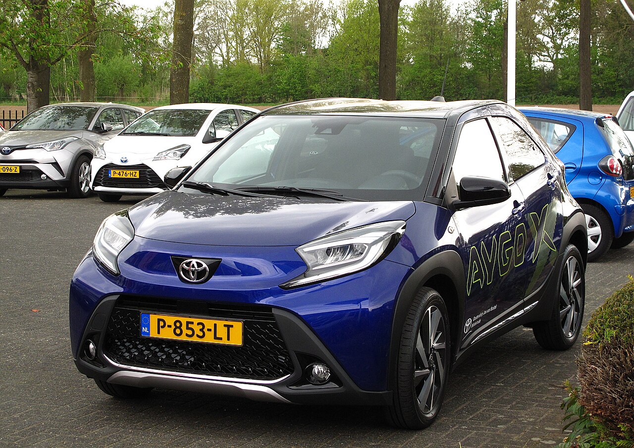
Toyota Aygo X AB70/KGB70 (2022) uses a 1.0 VVT-i petrol engine, with a five-speed manual or Multidrive CVT transmission. Its fuse protection is divided between a driver-side dashboard junction block, cartridge fuses on the rear of that panel, and two separate fuse boxes in the engine compartment, named type A and type B.
This guide covers the European 2022 petrol electrical layout. It does not apply to the earlier Aygo AB40, or to later Aygo X Hybrid models. The factory manual identifies 41 cabin positions, two optional alternatives in that cabin chart, four rear cartridge positions, two type A engine fuses and 30 type B engine fuses. All 79 documented rows and variants, including empty sockets, are retained below.
Where are the Toyota Aygo X 2022 fuse boxes?
Inside the car: park safely and switch the ignition and accessories off. In a left-hand-drive car, move the driver’s seat back, locate the access cover beneath the driver’s side of the dashboard and release its retaining tab. For right-hand-drive models, use the corresponding access side shown by the vehicle’s fuse cover. Match each name and rated amperage against the installed label before withdrawing the fuse with the supplied plastic puller.
Behind the cabin panel: four additional high-current cartridge positions supply the roof, windows and blower. Their numbering is independent of the 1-41 main cabin positions. Do not disconnect module wiring or try to replace large bolted links without the appropriate service procedure.
Under the bonnet: raise the bonnet and locate the two protected boxes close to the battery. With the ignition off, press the lid retaining tabs and lift the cover. Type A is a small additional fuse block; type B contains positions 1-30 for engine, brakes, power steering, lighting and wipers. Refit each lid firmly after inspecting it.
Passenger compartment fuse panel – positions 1-41
This complete cabin fuse list includes empty slots and the optional USB NO.1 at position 14 and S/ROOF at position 18. These are alternative equipment entries, not extra sockets. The new graphic below is a readable index of all 41 cabin fuse numbers and ratings, not a drawing of their physical geometry. Compare with the label fitted to your car.
| Pozycja | Amperaż [A] | Chroniony obwód / funkcja |
|---|---|---|
| 1 | – | Unoccupied on the documented 2022 manual chart; check the vehicle’s own fuse legend |
| 2 | 10 | MIR HTR – heated exterior mirrors and rear window |
| 3 | 20 | DOOR R/R – right rear door electrical systems |
| 4 | 7.5 | OBD – on-board diagnostics connector |
| 5 | – | Unoccupied on the documented chart; consult the car’s fuse legend |
| 6 | 20 | DOOR F/R – right front door electrical circuits |
| 7 | 20 | DOOR R/L – left rear door electrical circuits |
| 8 | 20 | DOOR F/L – left front door electrical circuits |
| 9 | 7.5 | DOME CUT – switched interior light circuit |
| 10 | 5 | ECU-DCC NO.1 – automatic headlights, wipers, indicators and driver assistance |
| 11 | 10 | ECU-DCC NO.2 – ABS, air conditioning, radio, instrument panel, locking and steering controls |
| 12 | – | Unoccupied on the documented chart; consult the car’s fuse legend |
| 13 | 15 | D/L – central locking, electronic key and steering lock |
| 14 | – | Unoccupied in the main manual assignment; see optional USB alternative below |
| 14 | 7.5 | USB NO.1 – USB charging outlet on selected cover labels; may not be fitted |
| 15 | 7.5 | ECU-ACC – engine/CVT management, mirrors, wireless charger and Stop & Start |
| 16 | 5 | SFT LOCK-ACC – automatic transmission shift lock |
| 17 | 10 | DOOR BACK – electric tailgate release and central locking |
| 18 | – | Unoccupied in the main manual assignment; see optional fabric roof alternative below |
| 18 | 30 | S/ROOF – optional retractable fabric roof; otherwise unoccupied |
| 19 | 15 | WIPER RR – rear windscreen wiper and washer |
| 20 | – | Unoccupied on the documented chart; consult the car’s fuse legend |
| 21 | 10 | ECU-IGR NO.1 – ABS/VSC, engine and CVT, climate control, windows and optional roof |
| 22 | 10 | ECU-IGR NO.4 – Stop & Start system |
| 23 | 7.5 | BKUP LP – reversing lamps, camera, cluster, radio and parking sensors |
| 24 | 10 | ECU-IGR NO.2 – climate control, headlamps, locks, radio and pre-collision system |
| 25 | 10 | A/BAG-IGR – SRS airbag control |
| 26 | – | Unoccupied on the documented chart; consult the car’s fuse legend |
| 27 | 5 | ECU-IGR NO.3 – ABS/VSC, traction control and tyre pressure monitoring |
| 28 | 10 | ECU-B NO.2 – climate, automatic lighting, charging and Stop & Start |
| 29 | 10 | STOP – brake lamps, ABS/VSC, engine controller and shift lock |
| 30 | 7.5 | ECU-B NO.1 – smart key, starting, immobiliser and steering lock |
| 31 | – | Unoccupied on the documented chart; consult the car’s fuse legend |
| 32 | 7.5 | AM2 – starter, immobiliser, smart key and Stop & Start |
| 33 | 5/10 | AM1 / STRG LOCK – 5 A conventional ignition switch or 10 A steering lock with smart key |
| 34 | 15 | HAZ – indicators and hazard lights |
| 35 | – | Unoccupied on the documented chart; consult the car’s fuse legend |
| 36 | 7.5 | DOME – cabin lighting |
| 37 | 15 | P/OUTLET NO.1 – 12 V accessory power outlet |
| 38 | – | Unoccupied on the documented chart; consult the car’s fuse legend |
| 39 | 25 | DOOR DBL/L – door circuits and central locking |
| 40 | – | Unoccupied on the documented chart; consult the car’s fuse legend |
| 41 | 5 | DCM – communication module, audio and reversing camera |
Cabin fuse box rear side – cartridge fuse positions 1-4
This rear-side cartridge fuse group is numbered separately from the main cabin 1-41 positions. The graphic below illustrates the four circuits and their amp ratings, not the physical shape of the fuse carrier. P/WINDOW (30 A) supplies the electric windows, HTR (40 A) the blower, and S/ROOF (30 A) is installed only with the fabric roof.
| Pozycja | Amperaż [A] | Chroniony obwód / funkcja |
|---|---|---|
| 1 | – | Unoccupied cartridge fuse socket on the rear of the cabin junction block |
| 2 | 30 | S/ROOF – retractable fabric roof, where factory-fitted |
| 3 | 30 | P/WINDOW – electric windows |
| 4 | 40 | HTR – heating and air-conditioning blower motor |
Engine compartment type A – positions 1-2
Type A contains BBC NO.3 (50 A) for Stop & Start and AMP NO.2 (20 A) for the optional JBL amplifier. A car without the relevant equipment may have a different occupancy.
| Pozycja | Amperaż [A] | Chroniony obwód / funkcja |
|---|---|---|
| 1 | 50 | BBC NO.3 – engine Stop & Start system |
| 2 | 20 | AMP NO.2 – optional JBL audio amplifier |
Engine compartment type B – positions 1-30
The fuse numbering shown below is from the European Toyota Aygo X 2022 owner’s manual. This drawing is the type B layout and must not be replaced by a superficially similar illustration for the previous Aygo. Large 80-100 A supplies, ABS, electric steering and smaller engine control fuses occupy different sections of the carrier.
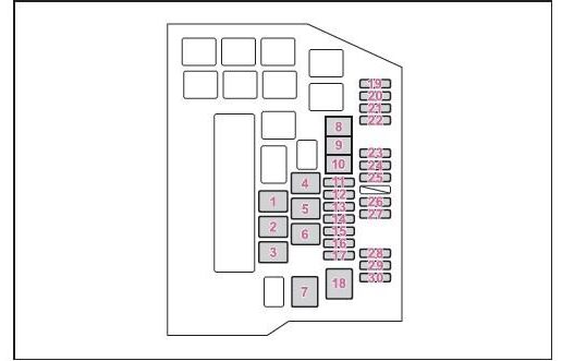
| Pozycja | Amperaż [A] | Chroniony obwód / funkcja |
|---|---|---|
| 1 | 100 | INP STD NO.1-2 – main supply to passenger seat, fabric roof, interior lights, diagnostics, ECU, doors and blower |
| 2 | 80 | INP STD NO.1-3 – main supply to rear wiper, reverse lights, ECU, SRS, stop lights, hazards and starter |
| 3 | 100 | INP STD NO.1-1 – power distribution block (PDB/IC) and heated mirrors |
| 4 | 80 | STD PI NO.1 – main integrated power distribution |
| 5 | 60 | EPS – electric power steering |
| 6 | 80 | SUB RB BATT – Stop & Start and optional JBL amplifier supply |
| 7 | 30 | FAN NO.1 – radiator cooling fan motor |
| 8 | 50 | ABS NO.1 – ABS and vehicle stability control (VSC) |
| 9 | 30 | BBC NO.1 – Stop & Start system |
| 10 | 30 | ABS NO.2 – secondary ABS and VSC control circuit |
| 11 | 30 | ST NO.1 – starter motor and starter supply |
| 12 | 20 | EFI-MAIN NO.2 – fuel injection and Stop & Start system |
| 13 | 20 | TOWING B – bicycle carrier electrical connection or optional equipment outlet |
| 14 | 20 | EFI-MAIN NO.1 – main fuel injection, cooling and Stop & Start supply |
| 15 | 10 | HORN – horn |
| 16 | 30 | WIPER – front windscreen wiper motor |
| 17 | 30 | D/C CUT – electronic injection power supply circuit |
| 18 | 30 | BBC NO.2 – Stop & Start supply |
| 19 | 10 | EFI NO.3 – fuel injection ECU and Stop & Start |
| 20 | 10 | EFI NO.5 – additional injection and Stop & Start circuit |
| 21 | 10 | ECU-IGP NO.3 – brake lamps, gateway, immobiliser, Stop & Start and heated seats |
| 22 | 7.5 | ECU-IGP NO.1 – automatic / Multidrive gearbox control, where fitted |
| 23 | 15 | DIM RH – right headlamp supply |
| 24 | 5 | BATT-S NO.1 – battery state sensor |
| 25 | 25 | IGP MAIN – washer and ignition circuit supply |
| 26 | 15 | DIM LH – left headlamp supply |
| 27 | 7.5 | EFI NO.1 – injection control and Stop & Start |
| 28 | 5 | ECU-IGP NO.2 – automatic transmission shift lock module |
| 29 | 7.5 | INJ – ignition coils and EFI injection controller |
| 30 | 15 | WASHER – windscreen washer pump and wiper control module |
Equipment and transmission differences
Manual versus Multidrive CVT: automatic versions may use ECU-IGP and SFT LOCK circuits not required by a manual gearbox. Smart key: cabin position 33 can be a 5 A AM1 supply or a 10 A STRG LOCK circuit. Use the exact marking on the installed fuse chart.
Stop & Start: BBC and SUB RB BATT circuits support engine restarting. Comfort equipment: a car without JBL audio or the folding fabric roof does not need the corresponding optional fuse. The same fuse number can be blank in another car.
Practical fuse checks for common Aygo X problems
12 V accessory socket has no power: inspect cabin position 37, P/OUTLET NO.1 (15 A), after unplugging accessories. USB charging not working: verify whether optional USB NO.1 is actually fitted at cabin position 14.
Brake lights out: cabin position 29, STOP (10 A), also serves ABS and engine signalling. Front wipers not working: type B engine position 16, WIPER (30 A). The washer pump has separate type B position 30 (15 A); the rear wiper has cabin position 19 (15 A).
Horn silent: check engine type B position 15, HORN (10 A). Headlamp failure: type B positions 23 DIM RH and 26 DIM LH, each 15 A. Blower stopped: inspect rear cabin cartridge position 4, HTR (40 A), before diagnosing the motor regulator.
Starting trouble: besides battery, starter and wiring, type B positions 11 ST NO.1 (30 A), 12 / 14 EFI-MAIN (20 A each) and 25 IGP MAIN (25 A) are relevant. Do not increase the fuse amperage when it repeatedly blows.
For another Toyota layout with different engine management and power distribution, see the Toyota Corolla E140/E150 fuse diagrams. The two cars’ fuse positions are not interchangeable.