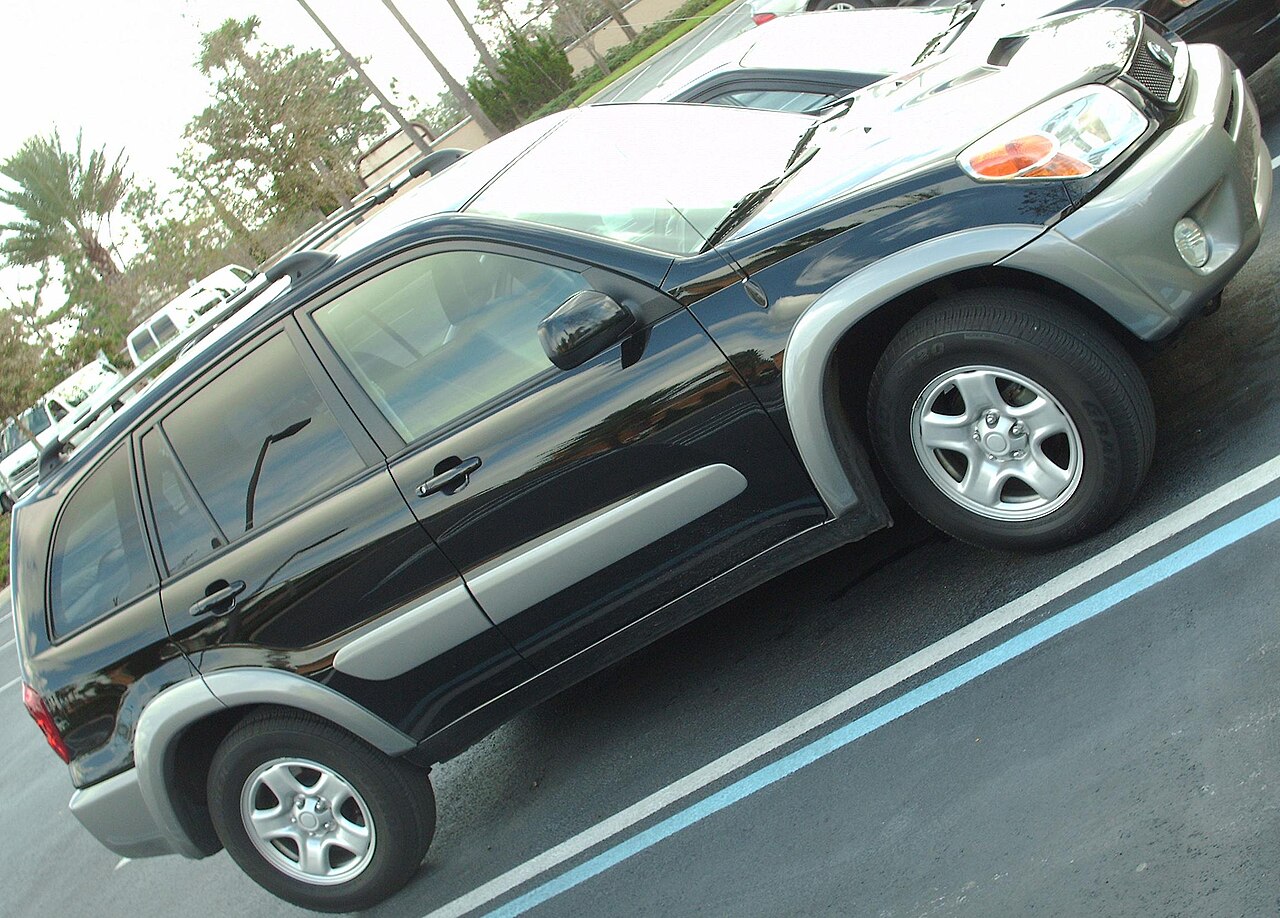
Toyota RAV4 II XA20 (2000-2005) was offered with three- and five-door bodies, petrol engines and, in European markets, D-4D diesels. Its power distribution uses an under-dashboard fuse panel, an auxiliary cabin relay group and a main engine-bay fuse and relay box. The illustrated assignments may vary by build date, engine, left/right-hand-drive layout and country.
This guide preserves all 68 individual source entries across three complete tables, including duplicate row numbers for different engine applications, ABS 40/50 A alternatives, unused sockets and relays. The three original diagrams are kept directly before the corresponding tables.
Important number-system difference: the 21 rows in the original cabin diagram are the order used by that reference chart, not necessarily the numbers moulded into every factory box. The US 2001 owner’s handbook OM42483U, for example, labels CIG 15 A as physical fuse 18 and POWER OUTLET 15 A as physical fuse 19, whereas this alternate 21-row chart labels those circuits as positions 2 and 3. The 2004-2005 North American numbering also changed. Identify the circuit by its printed CIG or POWER OUTLET label and amp rating on your car’s lid before attempting a replacement. Never assume positions with different numbering systems are the same physical cavity.
Where are the RAV4 XA20 fuse boxes?
Interior fuse carrier: switch off the ignition, disconnect electrical consumers and open the driver’s door. On a typical left-hand-drive European RAV4 XA20, locate the lower dashboard access cover near the driver’s knee. Unclip the small trim panel and compare the fuse map behind it with the owner’s handbook and the labels on the actual fuse holder. Right-hand-drive models have a different physical arrangement of dashboard control units and relays.
Auxiliary cabin relays: the separate relay plate can sit behind the lower dashboard trim rather than inside the visible blade-fuse row. Its R1-R5 notation is local to this panel.
Under the bonnet: with the engine off and radiator fan stopped, open the bonnet and locate the covered fuse block by the battery. Release the plastic clips and identify the high-current ABS, cooling and heater fuses along with the smaller engine-management fuses. High-current fusible links require the correct battery-isolation procedure. Refit the sealed lid after inspection.
Interior fuse chart – all 21 positions in the archived diagram
CIG (15 A) is the lighter socket while POWER OUTLET (15 A) supplies additional 12 V outlets. The original reference’s rows are position 2 and 3 respectively, but the 2001 US factory manual has a distinct physical numbering: 18 and 19. The same equipment discrepancy applies to other row numbers and must be checked against the car’s own card. The S-HTR 10 A slot can be unpopulated on North American 2001 vehicles that lack seat heaters.
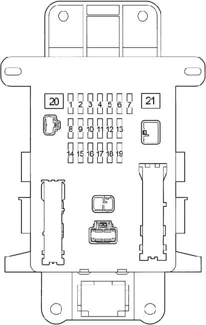
| Pozycja | Amperaż [A] | Chroniony obwód / funkcja |
|---|---|---|
| 1 | 10 | STOP – stop lamps including high-level stop light, ABS, shift lock, fuel injection and cruise control |
| 2 | 15 | CIG – front cigarette lighter 12 V socket |
| 3 | 15 | POWER OUTLET – auxiliary 12 V accessory sockets |
| 4 | 10 | S-HTR – heated seats if equipped; unpopulated in certain 2001 market variants |
| 5 | 7.5 | PANEL – instrument lighting, front fog lamp control, heated exterior mirrors and A/C |
| 6 | 15 | FR FOG – front fog lights |
| 7 | 10 | HORN – horn |
| 8 | 7.5 | TAIL – tail lights, number plate lights and gauge illumination |
| 9 | 15 | TAIL&PANEL – main supply for the TAIL and PANEL fuse circuits |
| 10 | 7.5 | ACC – audio, automatic selector shift lock, clock and electric door mirrors |
| 11 | 20 | DEF – heated rear window |
| 12 | 10 | GAUGE – reversing lights, cooling fan, A/C, automatic gearbox indicators and charging system |
| 13 | 7.5 | OBD – onboard diagnostics connector |
| 14 | 10 | IG2 – ignition, injection and starter functions, SRS airbag and charging lamp |
| 15 | 20 | DOOR – electric central door locking |
| 16 | 10 | MIR HTR – heated exterior mirrors |
| 17 | 15 | RR WIP – rear wiper and washer |
| 18 | 25 | WIP – front windscreen wiper and washer |
| 19 | 10 | ECU IG – emergency flashers, gauges, ABS, airbags, shift lock, cruise control, traction/stability controls |
| 20 | 30 | POWER – power windows and electric moonroof on equipped versions |
| 21 | 40 | AM1 – main accessory/ignition feed for CIG, outlets, wipers, heated rear window, ACC and GAUGE |
Separate cabin relay group R1-R5
These relays serve the horn, rear fog lamp, heated rear window, 12 V auxiliary outlets and electric window system. They are relay sockets rather than fuse links, so the current rating is represented as “-“. A vehicle without particular equipment can have an unoccupied relay location.
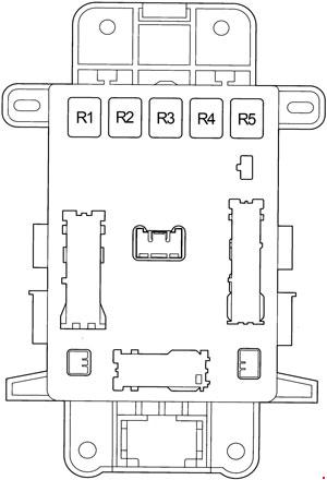
| Pozycja | Amperaż [A] | Chroniony obwód / funkcja |
|---|---|---|
| R1 | – | R1 – horn relay |
| R2 | – | R2 – rear fog light relay |
| R3 | – | R3 – rear window defogger relay |
| R4 | – | R4 – additional 12 V power outlet relay |
| R5 | – | R5 – electric power window relay |
Main engine compartment box – 42 fuse, shunt and relay entries
The under-bonnet distribution contains engine control, ABS/VSC, charging, ignition, headlights, cooling fans, fuel-pump controls and cabin blower supply. Engine socket 1 in this reference is a short pin/jumper rather than a standard replaceable fuse. Position 3 has two documented alternatives, A/F (20 A) or RADIO NO.2 (30 A); the proper allocation depends on fitted equipment. Position 24 likewise has H-LP CLN (30 A) for headlamp cleaning or diesel F-HTR (30 A) for fuel heating.
ABS 1 at position 26 is retained in two rows, rated 40 or 50 A by variant. Position 20 INJ has no amp value in the archived equipment listing and is not assigned one here. The R2/R6 fan relay naming is repeated in the original source; verify the actual relay identification by the installed vehicle’s fuse-box lid rather than interchanging relay modules.
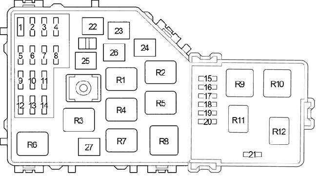
| Pozycja | Amperaż [A] | Chroniony obwód / funkcja |
|---|---|---|
| 1 | – | Factory short pin / electrical jumper; not a replaceable blade fuse |
| 2 | 5 | ALT-S – alternator and charging system monitor feed |
| 3 | 20 | A/F – air/fuel ratio oxygen sensor, engine/equipment-specific assignment of position 3 |
| 3 | 30 | RADIO NO.2 – sound system, alternate position 3 assignment |
| 4 | 20 | EFI1 – engine injection, automatic transmission oil temperature sensor, EFI2 and EFI3 supply |
| 5 | 30 | CUT – upstream supply for RADIO and DOME |
| 6 | 10 | HAZ – hazard warning flasher |
| 7 | 5 | EFI2 – engine fuel-injection controller feed |
| 8 | 30 | ABS 2 – ABS, VSC, traction control and brake assist |
| 9 | 10 | DOME – clock, cabin illumination and remote locking receiver |
| 10 | 30 | MAIN – main right and left headlamp supply |
| 11 | 10 | EFI3 – injection and emissions control |
| 12 | 15 | RADIO – car audio system |
| 13 | 5 | A/C – air conditioning control electronics |
| 14 | 15 | IGN – starting, engine and ignition controls |
| 15 | – | Unoccupied position on the depicted carrier |
| 16 | – | Unoccupied position on the depicted carrier |
| 17 | 10 | ETCS – electronic throttle control |
| 18 | 10 | H-LP RH – right-hand headlamp |
| 19 | 10 | H-LP LH – left-hand headlamp |
| 20 | – | INJ – fuel-injection circuit, rating not specified in this source variant |
| 21 | 5 | ST – starter control |
| 22 | 30 | AM2 – charging indicator, fuel injection, starting, SRS and IG2 feed |
| 23 | 40 | HTR – cabin heating and ventilation blower main supply |
| 24 | 30 | H-LP CLN – headlamp washer pump, position 24 on equipped versions |
| 24 | 30 | F-HTR – diesel fuel heater, alternate position 24 assignment |
| 25 | 30 | CDS – engine condenser cooling fan |
| 26 | 40 | ABS 1 – main ABS power, 40 A variant |
| 26 | 50 | ABS 1 – main ABS power, 50 A alternative |
| 27 | 30 | RDI – radiator cooling fan |
| R1 | – | R1 – EFI MAIN engine-control relay |
| R2 | – | R2 – cooling fan relay FAN NO.3 |
| R3 | – | R3 – ignition circuit relay IG2 |
| R4 | – | R4 – cooling fan relay FAN NO.2 |
| R5 | – | R5 – air/fuel ratio sensor relay |
| R6 | – | R6 – additional radiator fan relay, named FAN NO.2 in archived source |
| R7 | – | R7 – fuel-pump circuit-opening relay C/OPN |
| R8 | – | R8 – cabin heater blower relay HTR |
| R9 | – | R9 – starter relay ST |
| R10 | – | R10 – daytime running lamps relay DRL |
| R11 | – | R11 – engine control unit relay |
| R12 | – | R12 – unoccupied relay position |
Model year, petrol/diesel and market differences
RAV4 XA20’s European equipment chart, 2001 US handbook and later 2004-2005 US manuals cannot be aligned by row number alone. In North American manuals the fuses are numbered continuously across engine and cabin carriers, and some cabin labels use numbers in the teens, twenties or thirties instead of 1-21. Market changes also affect seat heating, DRL, fuel heater, headlamp cleaning, ABS/stability control and automatic gearboxes.
Diesel cars may use F-HTR where a petrol market uses another circuit. Do not use a North American gasoline-only manual as a direct assignment for a European 2.0 D-4D engine. The diagram on the installed fuse cover is the best match for diagnosing an individual car.
Common RAV4 II fuse checks and electrical faults
Cigarette lighter or 12 V socket dead: look for the labelled CIG (15 A) or POWER OUTLET (15 A) fuse in the actual interior panel. Do not identify the slot solely by a number from this cross-market chart. A damaged charger or metal debris in the socket can cause repeated failure.
Stop lamps failed: inspect the STOP circuit (10 A), then the brake pedal switch and bulbs. Front wipers stopped: check WIP (25 A) and the motor/linkage; the separate rear wiper uses RR WIP (15 A). Central door locking inoperative: the labelled DOOR circuit (20 A) protects the main door-lock control, but a single failed lock usually points to its actuator or door wiring.
Heater blower stopped: check the engine HTR main supply (40 A) and its relay, followed by the blower speed controller. No engine crank: engine ST (5 A) is a starter-control feed, and local engine relay R9 ST is also relevant; a good fuse does not rule out battery, starter solenoid or earth failures.
ABS indicator lit: check the vehicle-specific ABS 2 (30 A) and ABS 1 (40/50 A) circuit before reading fault codes. Never fit a 50 A link in a car whose factory fuse is 40 A.
Related older Toyota fuse-box guides include Toyota Corolla E110 and Toyota Avensis I T22. Their diagrams have different numbering and must not replace the RAV4 XA20 fuse card.