
Volkswagen Passat B3 Typ 35i (1988-1993) uses the CE2 central fuse and relay carrier beneath the driver’s dashboard. The original panel includes 22 numbered blade fuses, twelve main relay positions R1-R12, upper auxiliary positions R13-R24 and connector terminals on the back of the assembly.
The tables preserve all 89 original reference rows in five tables, including eleven common-circuit lookups, 22 main fuses, 24 relay positions and 32 rear-panel connector codes. A sixth table adds the separately documented 50 A diesel glow-plug fuse. Some positions and ratings vary by production year, engine, body style, ABS, A/C, automatic transmission and market. Follow the fuse-card and relay-holder numbering on your own car.
Where is the fuse box in a Passat B3?
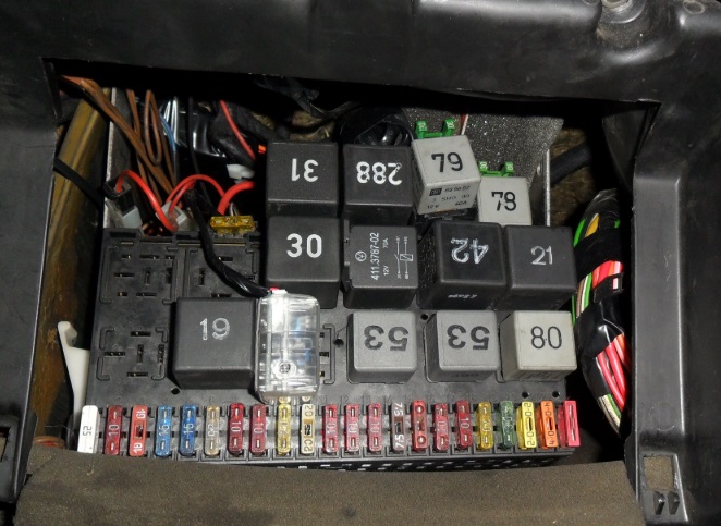
Turn the ignition off, remove the key, move the driver’s seat back and remove the knee panel or storage shelf beneath the steering wheel. The large CE2 carrier is mounted directly behind it. The 22 fuses occupy a numbered lower row and the standard relays sit in sockets R1-R12; additional relay and fuse holders can sit above them. Release retaining panels carefully without pulling on the rear wiring looms.
Numbers stamped on VW relay housings such as 18, 21, 53, 67, 80 or 99 identify the relay’s part/type, not its socket number. The actual R-position must be read from the panel and the factory wiring diagram. On right-hand-drive and special equipment cars, dashboard trim and installed auxiliary devices can differ.
Passat B3 – frequently checked fuses and relays
This first table is a convenience index, not a second physical set of fuses. It highlights the lighter, pump, radio, blower, wipers, rear demister and individual dipped/main-beam circuits.
| Pozycja | Amperaż [A] | Chroniony obwód / funkcja |
|---|---|---|
| 21 | 15 | Cigarette lighter and 12 V socket |
| 22 | 10 | Radio receiver |
| 18 | 20 | Petrol fuel pump and oxygen sensor heater |
| R12 | – | Petrol fuel pump relay, engine-dependent |
| 5 | 15 | Front windscreen wipers and washer |
| R8 | – | Intermittent wiper control relay |
| 6 | 20 | Fresh air heater blower |
| 9 | 20 | Heated rear window |
| 1 / 2 | – | Left and right dipped beam headlamps |
| 11 / 12 | – | Left and right main beam headlamps |
| 20 | 10 | Stop/brake lights |
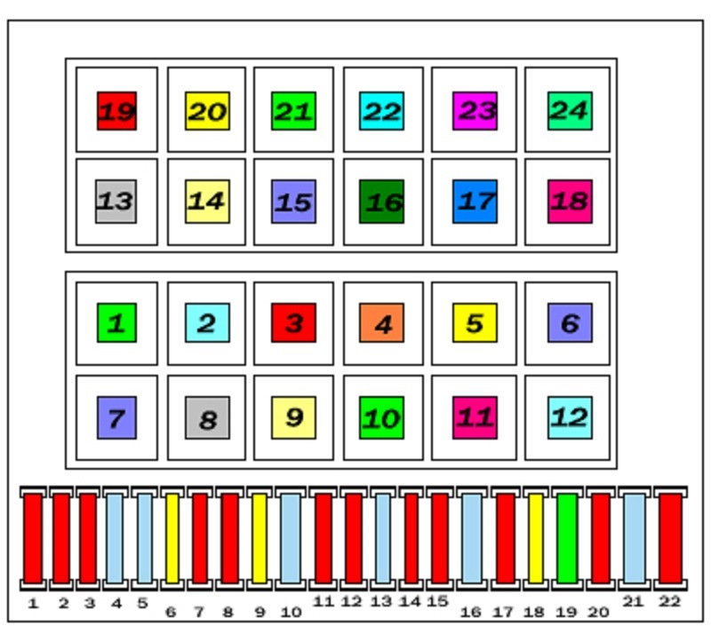
Complete 22-fuse CE2 panel
Fuse 21 (15 A) protects the cigarette lighter, interior lights and digital clock. Fuse 18 (20 A) protects the petrol fuel pump and oxygen-sensor heater. Fuse 4 (15 A) serves the rear wiper on a Variant estate and may not be populated in a saloon. Fuses 1/2 are the left/right dipped beams, and 11/12 are the corresponding high beams.
Fuse 10 can be unoccupied or assigned to fog lights depending on market. Fuse 13 can have 10 or 15 A horn protection; fuse 14 uses 10 or 15 A for reverse lights and heated washer jets. Check the rating fitted to the individual vehicle – do not simply select the highest alternative.
| Pozycja | Amperaż [A] | Chroniony obwód / funkcja |
|---|---|---|
| 1 | 10 | Left dipped-beam headlamp |
| 2 | 10 | Right dipped-beam headlamp |
| 3 | 10 | Instrument cluster and number plate lamps |
| 4 | 15 | Rear window wiper on Variant estate, not installed on saloon |
| 5 | 15 | Front windscreen wiper and washer motor |
| 6 | 20 | Fresh-air heater and air conditioner blower |
| 7 | 10 | Right front side/parking and tail lamps |
| 8 | 10 | Left front side/parking and tail lamps |
| 9 | 20 | Heated rear-window element |
| 10 | 15 / – | Fog lamps if fitted; position empty on some market fuse cards |
| 11 | 10 | Left main beam headlamp |
| 12 | 10 | Right main beam headlamp |
| 13 | 10 / 15 | Horn, rated 10 or 15 A depending on installed fuse card |
| 14 | 10 / 15 | Reversing lights and heated washer jets, 10 or 15 A by version |
| 15 | 10 | Fuel cut-off during engine overrun and engine-specific control |
| 16 | 15 | Instrument cluster and glovebox illumination |
| 17 | 10 | Direction indicators and hazard warning lights |
| 18 | 20 | Electric fuel pump and oxygen-sensor heating on petrol engines |
| 19 | 30 | Radiator fan and air-conditioning relay supply |
| 20 | 10 | Brake/stop lamps |
| 21 | 15 | Interior lighting, cigarette lighter and digital clock |
| 22 | 10 | Car radio |
Main relay sockets R1-R12
The lower carrier controls A/C, rear window wiping, horn, hazard indicators, front intermittent wipers and the petrol fuel pump, with additional safety equipment on some markets. R3 and R10 are unoccupied in this archived configuration. A printed housing number 67 or 80 often appears on the fuel pump relay but is not the socket position.
| Pozycja | Amperaż [A] | Chroniony obwód / funkcja |
|---|---|---|
| R1 | – | Air-conditioning relay |
| R2 | – | Rear wiper relay on Passat Variant estate |
| R3 | – | Unoccupied relay socket |
| R4 | – | X-contact electrical load reduction relay |
| R5 | – | Low coolant level warning controller |
| R6 | – | Hazard-warning flasher relay |
| R7 | – | Headlamp washer relay on Canadian-market cars; usually vacant elsewhere |
| R8 | – | Intermittent windscreen wiper and washer control relay |
| R9 | – | Seat belt reminder control unit on specified markets |
| R10 | – | Unoccupied relay socket |
| R11 | – | Horn relay |
| R12 | – | Fuel pump relay on petrol engines |
Additional upper positions R13-R24
These sockets mix relays, fuses, and automatic circuit breakers for ABS, electric windows, cruise control and automatic transmissions. R21 can carry a 30 A ABS pump fuse or a 20 A power-window circuit breaker; R22 protects the ABS valves at 30 A when fitted. R23 can contain a 5 A cruise-control fuse on specific market versions.
| Pozycja | Amperaż [A] | Chroniony obwód / funkcja |
|---|---|---|
| R13 | – | Automatic transmission reversing lamp protection |
| R14 | – | Radiator fan after-run control module |
| R15 | – | ABS hydraulic pump relay |
| R16 | – | ABS control relay |
| R17 | – | Unoccupied auxiliary relay position |
| R18 | – | Unoccupied auxiliary relay position |
| R19 | – | Air-conditioning relay |
| R20 | – | Starter interlock / reversing light relay for automatic gearbox |
| R21 | 20 / 30 | ABS pump protection 30 A or electric window 20 A circuit-breaker, equipment-dependent |
| R22 | 30 | ABS solenoid valve fuse, 30 A if equipped |
| R23 | 5 / – | Cruise control 5 A fuse or market-specific automatic shoulder belt protection |
| R24 | – | Unoccupied auxiliary position |
Rear side of CE2 – all 32 connector designations
The alphabetic codes identify wiring looms for headlights, body, instruments, engine bay, stalk switches, heating and rear lights. They are connector designations, not fuse sockets, hence the amperage column is marked “-“. Their colors and assigned wires can differ with special equipment. Only trained technicians should disconnect the rear CE2 loom.
| Pozycja | Amperaż [A] | Chroniony obwód / funkcja |
|---|---|---|
| A1 | – | A1 – yellow headlamp harness connection |
| A2 | – | A2 – yellow headlamp harness connection |
| B | – | B – unoccupied connector |
| C | – | C – yellow headlamp harness connection |
| D | – | D – green optional-equipment wiring |
| E | – | E – green instrument panel wiring |
| F | – | F – white right-side engine bay wiring |
| G1 | – | G1 – white right-side engine bay wiring |
| G2 | – | G2 – white right-side engine bay wiring |
| H1 | – | H1 – red steering column switch harness |
| H2 | – | H2 – red steering column switch harness |
| J | – | J – red steering column switch harness |
| K | – | K – black rear-body wiring harness |
| L | – | L – black rear-body wiring harness |
| M | – | M – black rear-body wiring harness |
| N | – | N – green air conditioning wiring |
| P | – | P – blue heated rear window wiring |
| Q | – | Q – blue instrument panel wiring |
| R | – | R – blue main light switch wiring |
| S | – | S – white right-side engine bay harness |
| T | – | T – green two-pin connector |
| U1 | – | U1 – blue instrument cluster connector |
| U2 | – | U2 – blue instrument cluster connector |
| V | – | V – green multifunction indicator MFA connector |
| W | – | W – green six-pin connector |
| X | – | X – green warning light indicator wiring |
| Y | – | Y – single terminal 30 battery-positive connector |
| Z1 | – | Z1 – single auxiliary connector |
| Z2 | – | Z2 – single terminal 31 earth connector |
| 30 | – | 30 – terminal 30 battery-positive connector |
| 30B | – | 30B – supplementary single connector |
| 31 | – | 31 – terminal 31 earth/ground connector |
Diesel glow plug main fuse S39 – 50 A
Diesel Passat B3 vehicles have a separate 50 A strip fuse near the engine-bay bulkhead, normally above the brake booster. This protects the glow plug heater supply and is not one of the 22 main dashboard fuses. Inspect both the strip and threaded holder for oxidation or overheating using the manufacturer’s battery isolation procedure.
| Pozycja | Amperaż [A] | Chroniony obwód / funkcja |
|---|---|---|
| S39 | 50 | Diesel glow plug preheating main power, separate strip fuse beside the bulkhead above the brake servo |
Practical Passat B3 electrical fault checks
12 V lighter or socket dead: start with fuse 21 (15 A) and inspect the socket for a short from loose metal. Front wipers work only intermittently or do not park: fuse 5 (15 A), relay R8, stalk and motor park-switch wiring should be checked.
Fuel pump silent on a petrol engine: inspect fuse 18 (20 A) and relay R12, then measure voltage at the pump. Rear wiper fault on Variant: check fuse 4 (15 A), relay R2 and tailgate loom; a saloon does not have that rear wiper.
ABS warning: R15/R16 as well as supplementary R21/R22 protection apply on ABS-equipped cars. Diesel hard starting: inspect S39 (50 A), its terminals, glow-plug relay and battery condition, rather than petrol fuel pump protection.
For the redesigned but related model, see Volkswagen Passat B4 (1993-1996). It uses the CE2 principle but can have different relay and optional equipment allocations.