
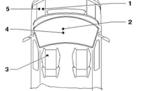
Volkswagen Transporter T5 Essentials (from September 2009 to 2014), including the revised T5.1, uses more than one fuse carrier. The most relevant are SF under the left front seat, SD in the engine-bay electronics housing, SB and SC in the central lower dashboard, and the high-current SA distribution block in the engine bay.
The tables below retain all 156 fuse entries and variants of the original Polish article, including manufacturer equipment notes and unoccupied positions. Where the old transcription merged footnote numbers into amperage (for example SC3 as “101 A”), the corrected values have been checked against a Volkswagen service fuse-position document for a 2012 Transporter CAAC. That document describes a specific engine and equipment configuration, not every van, so some variants are deliberately shown side by side. The vehicle’s factory fuse label and its wiring diagram take precedence.
Where are the fuse boxes in a VW Transporter T5.1?
SF under the left front seat: move the seat to gain access to the seat base, switch off the ignition and remove the designed front/side cover of the left seat pedestal. SF covers accessory and rear equipment, including three sockets, optional heaters, towbar wiring and sliding door systems. Seat-base access and installed fuse positions differ in vans with second battery or camper conversion.
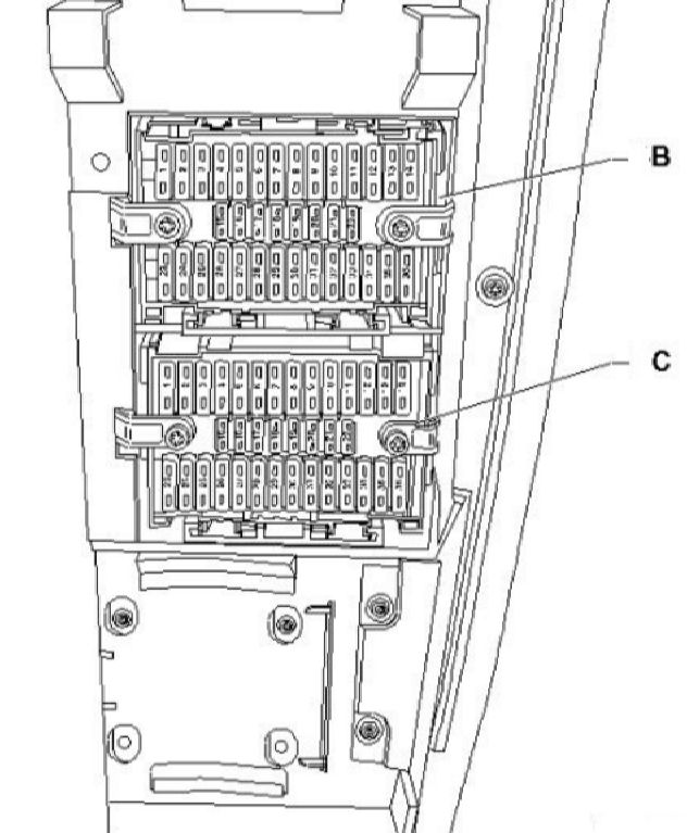
SB and SC in the centre dashboard: release the lower middle dashboard service cover. Two separate carriers, B and C, are mounted next to each other. Read the carrier’s letter first: SB10 and SC10 are different fuses even though the number is the same. Avoid damaging the retaining brackets when lowering a carrier.
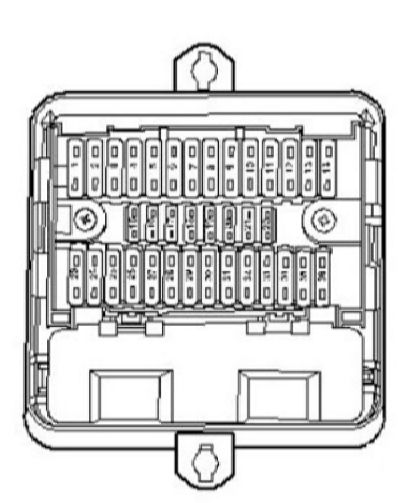
SD in the engine compartment: open the bonnet and locate the sealed engine electronics fuse housing. SD contains smaller engine, DSG, ABS, lighting and fuel-system fuses. Some VW layouts show SD in the left engine bay rather than the right described in older secondary charts; identify the covered electronics housing in the actual van.
SA high-current distribution: the main power link carrier near the engine-bay battery feeds alternator, ABS, fans and body wiring. The 50-225 A links require proper electrical isolation and, when applicable, professional servicing.
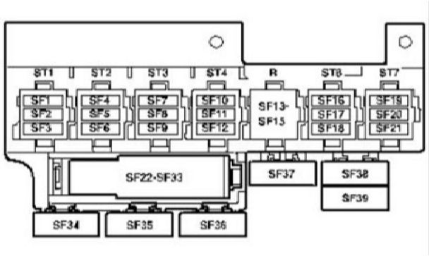
Fuse holder F – SF1 to SF36 under left seat
The original ESSENTIALS list shows 36 socket numbers, plus alternative documented SF10 and SF24 fuse values. SF11 (15 A) is the cigar lighter. SF22 and SF23 each supply a separate 15 A 12 V outlet. SF7’s precise rating varies with the outlet versus the optional 115/230 V inverter; check the actual vehicle fuse assignment card.
| Pozycja | Amperaż [A] | Chroniony obwód / funkcja |
|---|---|---|
| SF1 | 15 | Circuit not specified in the archived Essentials chart; check equipment label |
| SF2 | 3 | Circuit not specified in archived table; the VW 2012 CAAC example lists SF2 as 3 A |
| SF3 | 15 | Circuit not specified in archived Essentials chart; check equipment label |
| SF4 | 15 | Circuit not specified in archived Essentials chart; check equipment label |
| SF5 | 5 | Circuit not specified in archived Essentials chart; check equipment label |
| SF6 | 25 | Circuit not specified in archived Essentials chart; check equipment label |
| SF7 | 15 / 30 | 12 V accessory socket or optional 115/230 V power inverter, depending on equipment. A specific 2012 VW service chart distinguishes 15 A for a socket and 30 A for the inverter |
| SF8 | 20 / 25 | Heater control module or auxiliary heater receiver; some equipment lists 20 A rather than the 25 A archived rating |
| SF9 | 25 / 30 | Rear ventilation, fresh-air blower isolation relay J487 and voice amplification module; blower configurations can use 25 or 30 A |
| SF10 | 15 | Auxiliary heater relay J8 with the 15 A diesel / equipment-dependent assignment |
| SF10 | 30 | Alternative 30 A air-conditioning blower control and blower resistor circuit on the verified VW service diagram |
| SF11 | 15 | Cigarette lighter U1 |
| SF12 | 5 / 15 | Circuit not specified in the archived Essentials chart; source lists 15 A but a 2012 VW example also shows 5 A |
| SF13 | – | Unoccupied socket on the archived Essentials fuse chart |
| SF14 | – | Unoccupied socket on the archived Essentials fuse chart |
| SF15 | – | Unoccupied socket on the archived Essentials fuse chart |
| SF16 | – | Unoccupied socket on the archived Essentials fuse chart |
| SF17 | – | Unoccupied socket on the archived Essentials fuse chart |
| SF18 | – | Unoccupied socket on the archived Essentials fuse chart |
| SF19 | – | Unoccupied socket on the archived Essentials fuse chart |
| SF20 | – | Unoccupied socket on the archived Essentials fuse chart |
| SF21 | – | Unoccupied socket on the archived Essentials fuse chart |
| SF22 | 15 | 12 V socket number 2, U18 |
| SF23 | 15 | 12 V socket number 3, U19 |
| SF24 | 10 | Auxiliary coolant heater / roof ventilation relay depending on equipment, 10 A |
| SF24 | 15 | Alternative 15 A socket circuit, including 12 V socket number 4 (U20) in a VW service configuration |
| SF25 | 10 | Trailer recognition control module J345, circuit one |
| SF26 | 20 | Trailer recognition control module J345, circuit two |
| SF27 | 20 | Trailer recognition control module J345, circuit three |
| SF28 | 7.5 | Reversing camera controller J772 |
| SF29 | – | Unoccupied position |
| SF30 | 5 | Voice amplification control unit J656 |
| SF31 | – | Unoccupied position |
| SF32 | – | Unoccupied position |
| SF33 | 15 | Driver seat lumbar support adjustment switch |
| SF34 | 40 | Power sliding right door controller J731 |
| SF35 | 80 | Auxiliary battery isolation relay J7 |
| SF36 | 40 | 17-pin electrical connector and supply branch |
Fuse holder D – SD1 to SD36, engine electronics box
This panel contains main ECU control, ABS, fuel and cooling electronics, DSG mechatronics, headlamp controls and the pump and EGR circuits. SD10 has both a 5 A and a 15 A application depending on engine. Position SD32 also depends on diesel or petrol power distribution. The 2012 VW CAAC workshop diagram gives additional production-dependent circuits, so these rows must be checked against the van’s exact engine code.
| Pozycja | Amperaż [A] | Chroniony obwód / funkcja |
|---|---|---|
| SD1 | 5 | Radiator cooling fan controller J293 |
| SD2 | 5 | Additional coolant circulation pump relay J496 |
| SD3 | 5 | Crankcase breather heater N79 |
| SD4 | – | Unoccupied socket on the archived chart |
| SD5 | 15 | DSG dual-clutch mechatronics J743, selector lock solenoid N110 and selector lever |
| SD6 | 30 | ABS controller J104 |
| SD7 | – | Unoccupied in the archived Essentials layout; some later variants use a washer supply |
| SD8 | – | Unoccupied in the archived Essentials layout |
| SD9 | 5 | Engine ECU J623, permanent power supply |
| SD10 | 5 | Secondary air pump relay J299, petrol variant |
| SD10 | 15 | Boost control solenoid N75, EVAP N80, EGR cooler changeover N345 and boost solenoid N274, engine dependent |
| SD11 | 30 | Main-beam headlamp relay J12 |
| SD12 | 10 | Fuel metering valve N290 or fuel pressure regulation N276 |
| SD13 | 10 | Left HID gas-discharge headlamp controller J343 |
| SD14 | 5 | Fuel pump relay J17, supplementary fuel pump relay J832 and clutch pedal switch F36 |
| SD15 | 10 | Reverse lamp switch F4 |
| SD16 | 5 | Mass airflow sensor G70 and brake light switch F |
| SD17 | 5 | Traction control / ESP button E256 and ABS controller J104 |
| SD18 | 5 | Power steering controller J500 |
| SD19 | 5 | Clutch pedal switch F36 and MAF sensor G70 on applicable engine codes |
| SD20 | 5 | Engine ECU J623, ignition switched |
| SD21 | 5 | EGR valve N18 |
| SD22 | 10 | Fuel injectors N30-N33 for cylinders 1-4 |
| SD23 | 10 | Right HID headlamp controller J344 |
| SD24 | 5 | DSG mechatronic J743 and selector lever E313 |
| SD25 | 30 | Engine ECU J623 and ignition transformer N152 on applicable petrol variant |
| SD26 | 5 | Left daytime running light |
| SD27 | 10 | Continued coolant circulation pump V51 |
| SD28 | 15 | High-tone horn H2, especially taxi-equipment variants |
| SD29 | 5 | Right daytime running light |
| SD30 | 20 | Fuel-system pressurisation pump G6 and fuel pump relays J17/J832 |
| SD31 | 5 / 30 | Oxygen sensor heater Z19 and post-catalyst oxygen sensor heater Z29 |
| SD32 | 30 | Diesel engine ECU J623 or auxiliary electric fuel pump relay J49, depending on equipment; service diagrams show different 5/30 A branches |
| SD33 | 5 | Additional coolant pump relay J496 |
| SD34 | 5 | Onboard electrical supply controller J519 (T73b/59) |
| SD35 | – | Unoccupied position |
| SD36 | 30 | Additional coolant pump relay J496 |
Fuse holder B – SB1 to SB36 in centre dashboard
The upper/lower dashboard carrier includes steering angle, onboard supply control J519, starter and ignition switches, front lights, airbag supply, wipers, radio and diagnostic connector. Some lighting, tailgate and sliding-door functions require specific factory options, including an overhead console.
| Pozycja | Amperaż [A] | Chroniony obwód / funkcja |
|---|---|---|
| SB1 | 30 | Ignition-switched terminal 15 supply relay J329 |
| SB2 | 5 | Steering angle sensor G85 |
| SB3 | 10 | Body electrical power supply controller J519 (T73b/39) |
| SB4 | 5 | Rear wiring harness terminal 15a, lane-change assistance controllers J769/J770 |
| SB5 | 15 | Left dipped-beam headlamp L1 terminal 56b |
| SB6 | 15 | Left main-beam headlamp L1 terminal 56a |
| SB7 | 15 | Body supply controller J519 (T73a/66); equipment-specific roof console |
| SB8 | 15 | Tailgate controller J605, alarm horn H12, body controller J519 and electric sliding door controllers J558/J731, depending on specification |
| SB9 | 30 | Body supply controller J519 |
| SB10 | 10 | Wiper switch E22, rear wiper switch E34 and intermittent wash/wipe control E38 |
| SB11 | 5 | Number-plate lamp circuit X |
| SB12 | 5 | Main light switch E1 |
| SB13 | 7.5 | Supplementary Restraint System airbag controller J234 |
| SB14 | 25 | Steering column electronics controller J527 |
| SB15 | 7.5 | Fresh air blower switch E9 |
| SB16 | 5 | Body supply controller J519 ignition supply |
| SB17 | 5 | Rear fog light warning lamp K13 and rear fog lamp L46 |
| SB18 | 5 | Instrument cluster J285 permanent supply |
| SB19 | 5 | Ignition/starter switch D, terminal 86s |
| SB20 | 5 | On-board diagnostic connector U31 |
| SB21 | 10 | Starter relay J53 and engine ECU J623 |
| SB22 | 7.5 | Instrument cluster J285 and OBD connector U31 |
| SB23 | 30 | Ignition/start switch D terminal 50; some variants feed body control J519 separately |
| SB24 | 5 | Steering-angle sensor G85, ignition supply |
| SB25 | 7.5 | Fresh-air blower switch E9, permanent supply |
| SB26 | 30 | Main light switch E1, terminal 75X |
| SB27 | 15 | Right dipped headlamp L2 and beam terminal 56b harness |
| SB28 | 15 | Right main-beam headlamp L2 terminal 56a and instrument-cluster link |
| SB29 | 10 | Dual signalling inverter relay J741 |
| SB30 | 10 | Heated windscreen washer jets Z20/Z21 and rear or rear-door wiper motors V12/V92/V93 |
| SB31 | 30 | Body supply controller J519 (T73a/73) |
| SB32 | 30 | Body supply controller J519 (T73a/68) |
| SB33 | 30 | Radio R and radio-navigation display controller J503 |
| SB34 | 25 | Load-relief relay J59, supplying engine-bay fuse SD14 and SD20 |
| SB35 | 5 | Instrument and switch illumination distribution harness, terminal 58d |
| SB36 | 25 | Body supply controller J519 (T73b/13) |
Fuse holder C – SC1 to SC36 in centre dashboard
SC feeds trailer electronics, alarm and taxi-related options, 4MOTION rear differential locking, climate systems, instruments, heated seats and camper / auxiliary heater functions. SC3 is 10 A for Red Cross warning equipment or 15 A for taxi-alarm equipment in the verified workshop example, not the erroneous 101 A reproduced in secondary fuse charts.
| Pozycja | Amperaż [A] | Chroniony obwód / funkcja |
|---|---|---|
| SC1 | 15 | Trailer recognition J345 and 10-pin accessory connector T10bh/1 |
| SC2 | 5 | Interior monitoring receiver G305, anti-theft tilt controller J529 |
| SC3 | 10 / 15 | Red Cross emergency beacon switch E10 and warning K100 at 10 A; taxi meter G41 and taxi alarm controls use a 15 A alternative in the VW service chart |
| SC4 | 10 | Rear differential lock switch E121, differential controller J187 and 4MOTION controller J492 |
| SC5 | 5 / 10 | External six-pin accessory connector T6bn/5; 2012 service diagram specifies 10 A for this connector |
| SC6 | 5 | Oil level and temperature sensor G266 |
| SC7 | 10 / 30 | Rotating warning beacon switch E162 at 10 A or alternative alarm controller at 30 A |
| SC8 | 5 | Parking aid controller J446 |
| SC9 | 5 | Steering column control J527 and speed-control equipment |
| SC10 | 10 | Left/right headlamp levelling motors V48/V49 and instrument illumination regulator E20 |
| SC11 | 15 | Left sliding door controller J558; taxi warning equipment on particular service variants |
| SC12 | 5 / 30 | Left daytime running lamp L174; some configurations use an additional body supply feed |
| SC13 | 5 | Powertrain CAN-bus isolation relay J788 |
| SC14 | 5 | Right daytime running lamp L175 |
| SC15 | 5 | Mobile phone operating electronics controller J412 |
| SC16 | 7.5 | TV/navigation tuner and external multimedia interface R215/J415 |
| SC17 | 7.5 | Body control unit J519 and interior/luggage lamps |
| SC18 | 5 | Rear Climatronic controller E265, blower switch E179 and rear fan regulator G463 |
| SC19 | 5 | Automatic anti-dazzle rear-view mirror Y7 |
| SC20 | 10 | Body supply controller J519 |
| SC21 | 5 | Rain sensor G213 |
| SC22 | 5 | Air-conditioning pressure and air-quality sensors F129/G238 |
| SC23 | 7.5 / 10 | Residual-heat relay J708, auxiliary heater receiver R149 and camping equipment controller E153; rating may depend on specification |
| SC24 | 7.5 | Interior reading lights, front/rear cabin lamps and camping interior lighting |
| SC25 | 25 | Heated front-seat controller J396/J774 |
| SC26 | 10 | Tachograph G24, permanent feed |
| SC27 | 30 | Terminal 15 branch to engine-bay fuse SD13 and SD23 |
| SC28 | 5 | Mirror adjustment and mirror-heater switch E43/E231 |
| SC29 | 25 | Auxiliary heater controller J162 |
| SC30 | 5 | Camping equipment control/display E153 and supplementary heater relay J493 |
| SC31 | 5 / 25 | Electric sliding sunroof controller J245; some VW service variants use a 25 A branch |
| SC32 | 20 | Headlamp washer relay J39 |
| SC33 | 5 | Tachograph G24, ignition-switched |
| SC34 | 5 | Unoccupied in archived listing; 2012 workshop configuration may have a 5 A airbag clockspring/steering control supply |
| SC35 | 20 | Body supply controller J519 |
| SC36 | 5 | External ten-pin wiring connector T10bh/9 |
High-current fuse holder A – SA1 to SA9
SA is the high-amperage distribution unit in the engine compartment. The available service drawing lists variant ratings for alternator output, second battery charging, auxiliary fan and main positive supply branches; not every Transporter has the same configuration. No circuit should be bridged or fitted with a higher fuse merely because another vehicle is listed with that value.
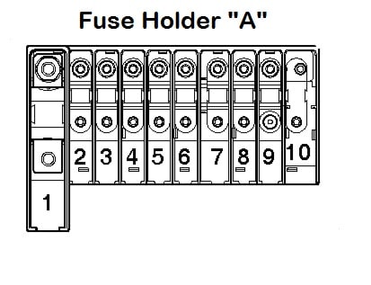
| Pozycja | Amperaż [A] | Chroniony obwód / funkcja |
|---|---|---|
| SA1 | 175 / 225 | Alternator main link: 175 A or 225 A according to alternator and production variant |
| SA2 | 125 | Ignition load-relief relay J59 and main harness positive distribution to SB9/SB14 |
| SA3 | 50 / 100 | Auxiliary battery isolation J7 (50 A) or second battery charger J713 (100 A), depending on installation |
| SA4 | 70 | Main engine compartment terminal 30 positive supply |
| SA5 | 50 | ABS main power circuit, linked to SD6 |
| SA6 | 50 / 60 | Glow-plug timing controller J179 (60 A) or secondary air-pump relay J299 (50 A), depending on engine |
| SA7 | 100 | Radiator fan controller J293, high-current supply |
| SA8 | 40 / 50 / 100 | Multiple passenger-compartment positive distribution feeds and radiator fan supplies, 40/50/100 A depending on build and equipment |
| SA9 | 100 | Main harness terminal 30 positive connection B272/B299 |
Important T5 equipment and engine code differences
The diagrams apply primarily to the T5 ESSENTIALS service arrangement revised from September 2009. VW made further changes in later years, including additional electronics and fuse positions in some models. Engine codes CAAA, CAAB, CAAC and CCHA use specific diesel circuits, while the AXA petrol engine has different fuel and exhaust control wiring. Taxi, emergency service, camper and double-battery versions require dedicated fuse assignments.
Factory documents list some fuse alternatives by terminal and equipment option rather than simply by year. A blank slot in an unconverted van may carry a fitted circuit in a camper or a vehicle with power sliding doors. The 2012 service manual used to clarify merged annotations here describes a CAAC engine with KUP gearbox, so it should not override the label of a different vehicle.
Common Transporter T5 electrical faults
Cigarette lighter dead: inspect SF11 (15 A) under the left front seat. Second and third 12 V sockets: look at SF22 and SF23 (15 A each). A fused aftermarket camper circuit may not use the factory assignments.
Radio or navigation inoperative: SB33 (30 A) powers the original radio/nav controller in the documented circuit. Rear sliding door stopped responding: inspect the relevant 40 A SF34 for the right power sliding door or the equipment-specific SC11 for the left, and diagnose the door motor and wiring.
Cooling fan warning: SD1 supports the radiator fan controller; SA7 protects a major high-current fan feed. ABS warning: SD6 is a 30 A ABS controller feed in the archived diagram, while SA5 is a high-current ABS supply. If these are correct, use VW diagnostic trouble codes before replacing parts.
Engine no-start: check the starter and engine controller supply for the fitted engine, including SD9/SD20 and SB21/23 where applicable. A faulty ignition switch or relay can give similar symptoms. Diesel glow plug issues: SA6 may feed the glow-control system, but it must not be confused with the petrol secondary-air pump variation.
For a separate manufacturer and generation, the English Ford Galaxy Mk2 guide illustrates a different multi-carrier layout. Its positions are not interchangeable with Volkswagen SF, SD, SB, SC or SA fuse numbers.