
BMW 1 Series F20/F21 (2011-2019) is the second-generation 1 Series hatchback. The F20 has five doors and the F21 has three. It was sold with a wide range of petrol and diesel engines, including 114i, 116i, 118i, 120i, 125i, M135i and M140i plus diesel 114d, 116d, 118d, 120d and 125d.
Fuse and power distribution is spread across the engine compartment, additional DME/DDE modules, the passenger-compartment Body Domain Controller (BDC) and several luggage-compartment points. Assignment varies with production date, engine, transmission, xDrive and equipment, so the original BMW fuse assignment card for the vehicle is essential.
Two fuse numbering schemes appear for the main under-bonnet block. A BMW fuse card labels the positions 18-70, while another diagram numbers their physical locations 1-53. In the appropriate mapped arrangement, BMW fuse 66 equals local position 49 and BMW fuse 69 equals local position 52. The last column of the first table retains that alternative slot number for every row.
Where are the BMW F20/F21 fuse boxes?
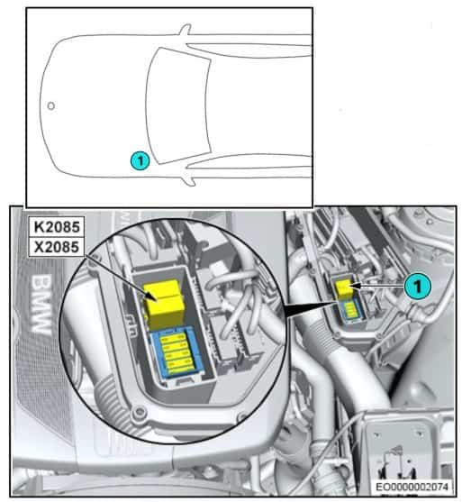
Engine compartment: with the ignition off, open the bonnet and locate the main fuse box beneath the protective plastic cover on the right-hand side of a left-hand-drive vehicle. The high-current FL1-FL6 block is adjacent to it. Selected engines have another electronic control fuse block, with certain diesel installations using a left-side engine-bay DDE carrier.
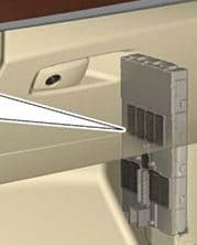
Passenger compartment: the Body Domain Controller (BDC) sits near the front passenger-side A-pillar / lower dashboard trim. Carefully release the appropriate trim according to the fitted vehicle. Unlike a simple fuse carrier, the BDC also performs body-control and relay functions, so avoid unnecessary module disconnection.
Luggage compartment: open the tailgate and remove the right-hand side trim access panel to reach the rear electronics. Other power distribution components are under the boot floor close to the battery. BMW often supplies its individual fuse card with pictograms in this area, which is the preferred reference for model-specific allocations.
Main engine-bay fuse box – BMW positions 18-70
This carrier has 53 physical slots. Some reference images use BMW identifiers 18-70; others use local position numbers 1-53. The two-number scheme is displayed without changing fuse amperage or removing variant-specific vacant slots.
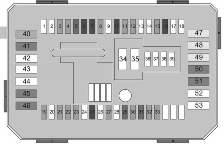
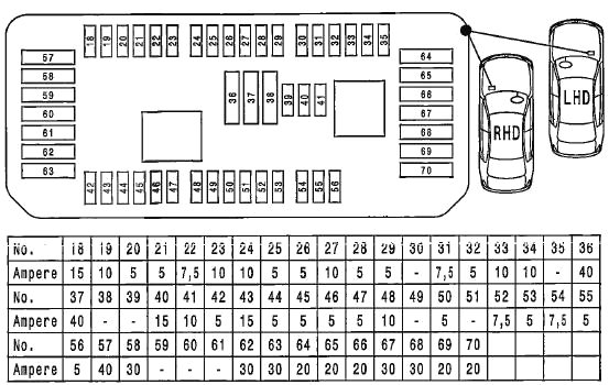
| Pozycja | Amperaż [A] | Chroniony obwód / funkcja |
|---|---|---|
| 18 | 15 / unused | Alternative diagram position 1. OBD diagnostic connector in one layout; unused on the other |
| 19 | 10 / unused | Alternative diagram position 2. Engine control circuit in one layout; unused on the other |
| 20 | 5 | Alternative diagram position 3. Audio head unit / roof electronics and other control module according to equipment |
| 21 | 5 / unused | Alternative diagram position 4. Control module on one diagram; unused on the other |
| 22 | 7.5 | Alternative diagram position 5. Central locking, passenger mirror and cabin lighting |
| 23 | 10 | Alternative diagram position 6. Main DDE relay / engine management depending on engine |
| 24 | 10 | Alternative diagram position 7. Automatic gearbox controller; on xDrive variants also 4WD control functions |
| 25 | 5 | Alternative diagram position 8. Touchbox / multimedia, possibly body controller, ABS/DSC and parking module |
| 26 | 5 / unused | Alternative diagram position 9. Seat heating on selected installations; otherwise unused |
| 27 | 10 | Alternative diagram position 10. Seat adjustment and lumbar support |
| 28 | 5 | Alternative diagram position 11. Front lamps, rain sensor and interior illumination |
| 29 | 5 | Alternative diagram position 12. Coolant pump or isolating relay / DSC, depending on layout |
| 30 | unused | Alternative diagram position 13. Unused position on typical installation |
| 31 | 7.5 / unused | Alternative diagram position 14. Equipment-dependent position, unused on some diagrams |
| 32 | 5 | Alternative diagram position 15. xDrive transfer case or security electronics according to equipment |
| 33 | 10-15 | Alternative diagram position 16. Coolant pump, air conditioning compressor and auxiliary coolant pump with variant-specific rating |
| 34 | 10 / unused | Alternative diagram position 17. Safety systems / seat belts on one variant; unused on the other |
| 35 | unused | Alternative diagram position 18. Typically unused |
| 36 | 40 / 5 | Alternative diagram position 19. High-current circuit 40 A on one layout; auto-dimming mirror 5 A on another |
| 37 | 40 / unused | Alternative diagram position 20. High-current circuit on one layout; unused on another |
| 38 | 5 / unused | Alternative diagram position 21. Driver assistance system in selected configurations |
| 39 | 5 / unused | Alternative diagram position 22. Cruise control in selected configurations |
| 40 | 15 / 5 | Alternative diagram position 23. Exterior lighting 15 A or crankcase breather heater / coolant shut-off valve 5 A |
| 41 | 10 / unused | Alternative diagram position 24. Equipment-dependent position, unused in certain variants |
| 42 | 5-10 | Alternative diagram position 25. Auto-dimming mirror or steering-column switch module, version dependent |
| 43 | 15 / unused | Alternative diagram position 26. Equipment-dependent circuit, unused in some variants |
| 44 | 5 | Alternative diagram position 27. Camera-based driver assistance / active steering, or instrument cluster on alternative layout |
| 45 | 5 / unused | Alternative diagram position 28. Cruise control on one diagram; unused on another |
| 46 | 5-7.5 | Alternative diagram position 29. Crankcase breather heater / coolant valve or instrument cluster, variant dependent |
| 47 | 5 | Alternative diagram position 30. Vehicle sound generator (NVE) or glovebox / dashboard lighting, depending on equipment |
| 48 | 7.5-10 | Alternative diagram position 31. Steering column switch module or gear selector, configuration dependent |
| 49 | 5 / unused | Alternative diagram position 32. Electric power steering (EPS) in one variant; unused in another |
| 50 | 5 | Alternative diagram position 33. Instrument cluster or air quality sensor, depending on diagram |
| 51 | unused | Alternative diagram position 34. Typically unused |
| 52 | 7.5 / unused | Alternative diagram position 35. Instrument cluster on one layout, unused on another |
| 53 | 5 / unused | Alternative diagram position 36. Glovebox, trim and footwell lighting on selected configurations |
| 54 | 7.5 / unused | Alternative diagram position 37. Gear selector on one layout; unused on another |
| 55 | 5 / unused | Alternative diagram position 38. Electric power steering on one layout; unused on another |
| 56 | 5 / unused | Alternative diagram position 39. Air quality sensor / ventilation on selected installations |
| 57 | 40 | Alternative diagram position 40. Fuse box power distribution and selected exterior lighting circuits |
| 58 | 30 | Alternative diagram position 41. Dynamic Stability Control (DSC) |
| 59 | unused | Alternative diagram position 42. Typically unused |
| 60 | unused | Alternative diagram position 43. Typically unused |
| 61 | unused | Alternative diagram position 44. Typically unused |
| 62 | 30 | Alternative diagram position 45. Roof and body circuit on related installations; may be unused on F20/F21 |
| 63 | 30 | Alternative diagram position 46. xDrive transfer case on models equipped with four-wheel drive |
| 64 | 20 | Alternative diagram position 47. Front passenger seat heating |
| 65 | 20 | Alternative diagram position 48. Driver seat heating |
| 66 | 20 | Alternative diagram position 49. Front cigarette lighter / 12 V outlet |
| 67 | 30 | Alternative diagram position 50. Driver electric seat and its control module |
| 68 | 30 | Alternative diagram position 51. Passenger electric seat and its control module |
| 69 | 20 | Alternative diagram position 52. Additional 12 V outlet; some later original fuse cards show different ratings |
| 70 | 20 / unused | Alternative diagram position 53. Supplementary heating on one version; unused on the other |
Cigarette lighter and 12 V sockets
For the typical documented arrangement the front cigarette lighter is BMW fuse 66 (20 A), local position 49. The supplementary 12 V socket is BMW fuse 69, local position 52, usually 20 A. Later card versions can differ, so confirm the exact fuse map before fitting a replacement.
| Pozycja | Amperaż [A] | Chroniony obwód / funkcja |
|---|---|---|
| 66 | 20 | Alternative diagram position 49. Front cigarette lighter / primary 12 V socket |
| 69 | 20 (typical configuration) | Alternative diagram position 52. Additional 12 V socket, rating depends on the individual fuse card |
Engine compartment high-current fuses FL1-FL6
The main FL block feeds high-load functions such as electric steering, DSC, the heater blower and supplementary heating. These are not standard miniature blade fuses and require the correct vehicle isolation and electrical service procedure.
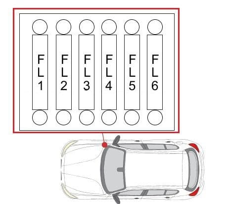
| Pozycja | Amperaż [A] | Chroniony obwód / funkcja |
|---|---|---|
| FL1 | 50 / 80 / 125 | Power isolation relay / main supply; version-dependent rating |
| FL2 | 125 | Electronic power steering (EPS) |
| FL3 | 100 | Supplementary electric heater |
| FL4 | 40 | Diesel fuel filter heater |
| FL5 | 40 | Dynamic Stability Control (DSC) |
| FL6 | 40 | Climate blower motor |
DME/DDE engine electronics fuse blocks
Selected engine variants have supplementary engine-electronics fuses. The DME petrol and DDE diesel control units, cooling pump and related relay arrangements do not all use the same physical layout. Use the installed engine code and carrier drawing.
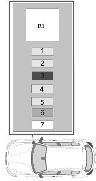
| Pozycja | Amperaż [A] | Chroniony obwód / funkcja |
|---|---|---|
| 1 | 20 | Engine control unit |
| 2 | 20 | Engine control unit |
| 3 | 10 | Engine control unit |
| 4 | 15 | Engine management / actuators depending on engine |
| 5 | 20 | Engine management / ignition system according to version |
| 6 | 40 | Engine control system |
| 7 | 50 | Electric coolant pump |
| R1 | – | Main DDE relay on applicable diesel versions |
Additional diesel DDE fuse carrier
On some diesel variants another under-bonnet block protects the common-rail fuel pressure valve, metering control, camshaft sensor, boost control, lambda sensor, air-flow sensor, oil level sensing and EGR systems. This block varies with the engine and is not allocated a universal, complete fuse numbering in the source chart.
Body Domain Controller in the passenger compartment
The BDC combines body electronics, relays and fuse functions. The listed positions include power windows, central locking, the diagnostic socket, lighting controls and the horn. Optional modules can leave some sockets vacant.
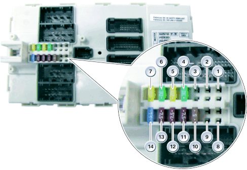
| Pozycja | Amperaż [A] | Chroniony obwód / funkcja |
|---|---|---|
| 1 | – | Unused position |
| 2 | – | Unused position |
| 3 | – | Unused position |
| 4 | 30 | Passenger power window |
| 5 | 20 | Central locking |
| 6 | 30 | Driver power window |
| 7 | version dependent | Central locking, rating varies by installation |
| 8 | – | Unused position |
| 9 | – | Unused position |
| 10 | 5 | Lighting switch panel, driver assistance, steering column module and climate system |
| 11 | 7.5 | Rear electronics module (REM) or headlamp control, version dependent |
| 12 | 7.5 | OBD diagnostic connector and selected climate / DSC circuits |
| 13 | 5 | Telematics, door-handle access electronics, equipment dependent |
| 14 | 15 | Horn |
Other BDC relay functions can include power windows, door locks, headlamp washers, starter, horn and wiper control. A relay should not be replaced solely by matching its visual position on another vehicle.
Rear luggage compartment fuses
Multiple power distribution points may be present under the boot floor and behind the right-hand trim, including a battery-adjacent high-current assembly. The original BMW card often identifies circuits by pictograms rather than long text.
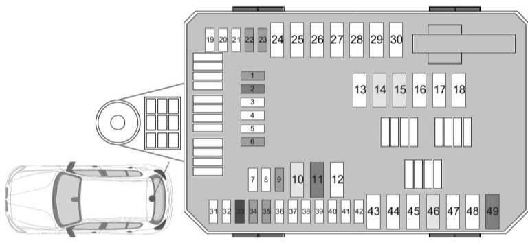
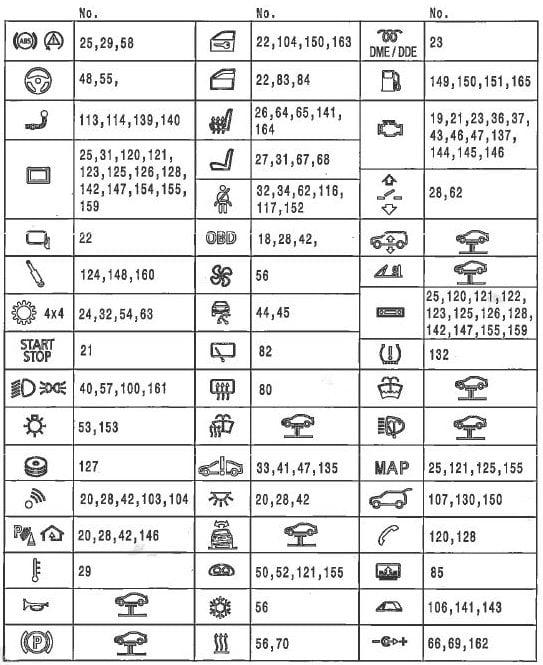
Additional luggage-compartment fuse carrier, local positions 1-49
Do not confuse the 1-49 local numbering of this rear carrier with the local 1-53 main engine box or with the BMW fuse card, which contains another range for the rear main distribution group.
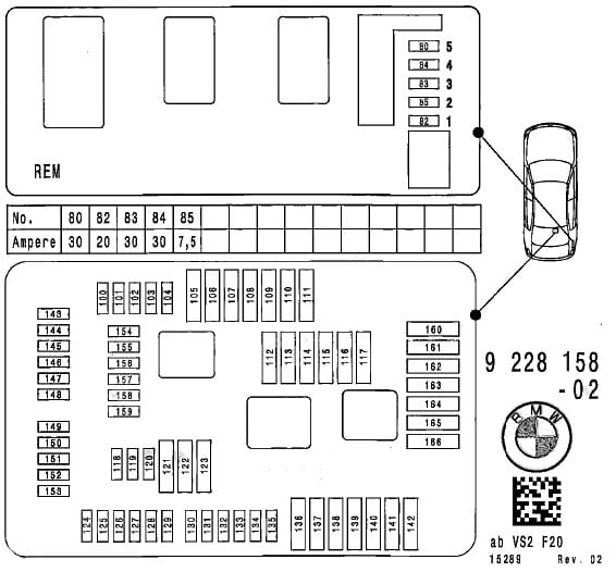
| Pozycja | Amperaż [A] | Chroniony obwód / funkcja |
|---|---|---|
| 1 | 5 | Camera control module |
| 2 | 15 | Radio control module |
| 3 | – | Unused position |
| 4 | – | Unused position |
| 5 | – | Unused position |
| 6 | 5 | Audio system |
| 7 | – | Unused position |
| 8 | – | Unused position |
| 9 | 5 | Telematics |
| 10 | 20 | Radio controller / multimedia head unit |
| 11 | 30 | Hi-Fi amplifier |
| 12 | – | Unused position |
| 13 | – | Unused position |
| 14 | 20 | Towbar / trailer module |
| 15 | 20 | Towbar / trailer module |
| 16 | – | Unused position |
| 17 | – | Unused position |
| 18 | – | Unused position |
| 19 | – | Unused position |
| 20 | – | Unused position |
| 21 | – | Unused position |
| 22 | 5 | Alarm siren / interior sensor, depending on variant |
| 23 | 5 | Remote-control receiver and vacuum leakage diagnosis |
| 24 | – | Unused position |
| 25 | – | Unused position |
| 26 | – | Unused position |
| 27 | – | Unused position |
| 28 | – | Unused position |
| 29 | – | Unused position |
| 30 | – | Unused position |
| 31 | – | Unused position |
| 32 | – | Unused position |
| 33 | 10 | Audio system |
| 34 | 5 | DVD player, if fitted |
| 35 | 5 | Multimedia base unit / module, equipment dependent |
| 36 | – | Unused position |
| 37 | – | Unused position |
| 38 | – | Unused position |
| 39 | – | Unused position |
| 40 | – | Unused position |
| 41 | – | Unused position |
| 42 | – | Unused position |
| 43 | – | Unused position |
| 44 | – | Unused position |
| 45 | – | Unused position |
| 46 | 20 | Trailer electrical socket / controller |
| 47 | – | Unused position |
| 48 | – | Unused position |
| 49 | 30 | DC-DC converter |
Battery-adjacent high-current block FL1-FL5
This battery-connected distribution block feeds the rear electronic module and other power distribution branches. Disconnecting or testing these high-current links requires appropriate safety procedures.
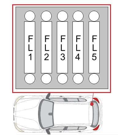
| Pozycja | Amperaż [A] | Chroniony obwód / funkcja |
|---|---|---|
| FL1 | 50 | Rear electronic module supply |
| FL2 | 10 | Fuse box supply |
| FL3 | 10 | Power distribution |
| FL4 | 125 | Main power distribution |
| FL5 | 125 | Integrated power module |
Frequently checked BMW F20/F21 fuses
Front 12 V outlet dead: check BMW fuse 66, alternative local position 49, typically 20 A. For the additional socket, check fuse 69 / local position 52. Disconnect chargers and other accessories before inspecting the outlet contacts for conductive debris.
DSC faults: the documented main fuse 58 (30 A) protects a DSC circuit, with further high-current protection at FL5. Check the relevant control unit fault codes and wiring instead of assuming a fuse failure.
Electric seat or seat heater stopped: main fuses 64 (passenger heat), 65 (driver heat), 67 (driver adjustment) and 68 (passenger adjustment) are useful starting points when that equipment is present.
xDrive or cooling-pump issues: main fuse 63 (30 A) can protect the transfer case on vehicles fitted with xDrive; the electric coolant pump may have an additional 50 A fuse in its engine electronics module. Neither circuit exists in every model.
Repeated blown fuses: inspect the consumer and wiring. Never use a higher-rated fuse to avoid investigating a short circuit. The source charts cover several engine and facelift configurations, so an empty socket is not automatically a missing fuse.
For related diagrams, see BMW fuse box diagrams. Assignments from other BMW models cannot be substituted without checking the actual wiring configuration.