
BMW 5 Series F10, F11, F07 and F18 (2010-2017) includes the saloon, Touring estate, Gran Turismo and extended-wheelbase variants. These BMWs use multiple electrical distribution blocks in the glovebox, luggage compartment and engine bay. Additional fuses or battery modules are installed on certain engine, xDrive and high-equipment versions.
Individual fuse positions and ratings may vary with production year, engine, transmission, country and equipment such as Soft Close, Night Vision, rear climate control, active suspension and parking heater. The original BMW fuse chart carried in the vehicle is the primary reference where allocations differ.
BMW F10/F11 fuse box locations and access
Passenger glovebox: switch off the ignition and open the glove compartment. Release the service cover or access panel to reach the cabin fuse carrier. The complete chart below covers positions 1-71. Avoid pulling the glovebox trim abruptly because wiring and cabin electronic modules may be nearby.
Right luggage compartment: open the boot or Touring tailgate and fold back the right-side trim cover. The main rear fuse and relay unit is behind the lining. The factory fuse assignment chart may be stored near this carrier.
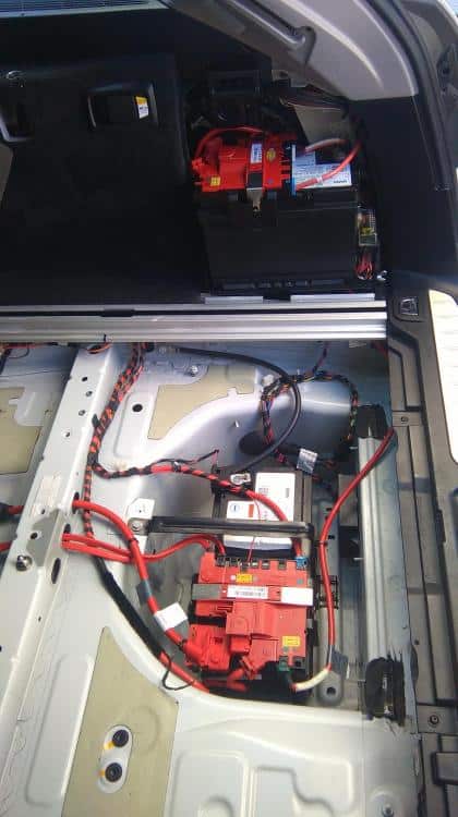
At the battery: certain variants have further fuse carriers, an auxiliary battery and high-current links close to the battery positive terminal. These need correct isolation and service procedures before work.
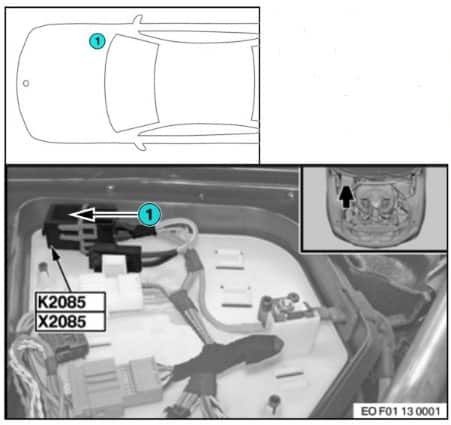
Under the bonnet: locate the protected fuse and relay components on the right side of the engine compartment. In diesel vehicles, an additional DDE main relay and selected steering or engine management fuses may be fitted under the cover.
Additional engine-bay fuses and main DDE relay
These include electromechanical steering, engine electronics and the diesel DDE main relay. Not all installations use the same fuse carrier or the same 125 A high-current circuit.
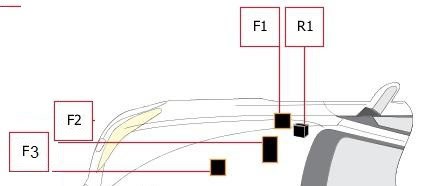
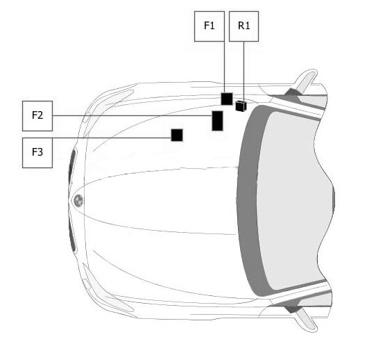
| Pozycja | Amperaż [A] | Chroniony obwód / funkcja |
|---|---|---|
| 1 | 5 | Electromechanical power steering |
| 2 | 30 | Power distribution and engine electronics |
| 3 | 125 | Electromechanical power steering / capacitor, depending on configuration |
| R1 | – | Main DDE relay on diesel engines |
Glovebox fuse box – complete positions 1-71
The main cabin panel protects wipers, climate control, DSC, electronic access, the instrument cluster, seats, the cigarette lighter and various body modules. Unused slots and alternative amperages are preserved in the table.
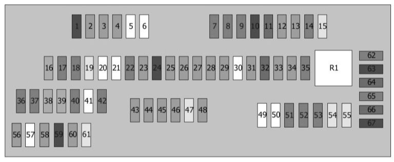
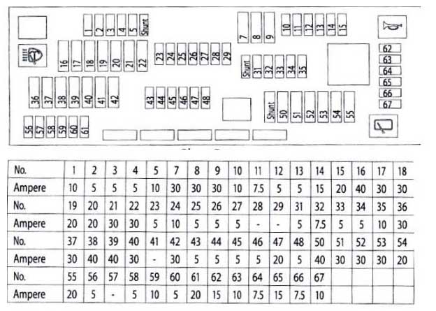
| Pozycja | Amperaż [A] | Chroniony obwód / funkcja |
|---|---|---|
| 1 | 10 | FRM footwell module |
| 2 | 5 | Dynamic Stability Control (DSC), door controller |
| 3 | 5 | Central gateway / data-bus interface and OBD diagnostic connector |
| 4 | 5 | Equipment-dependent control module |
| 5 | – | Unused position |
| 6 | – | Unused position |
| 7 | 30 | Junction Box electrical distribution |
| 8 | 30 | Junction Box electrical distribution |
| 9 | 30 | Junction Box electrical distribution |
| 10 | 10 | Instrument cluster |
| 11 | 7.5 | Heating and air-conditioning controller |
| 12 | 5 | Glovebox light |
| 13 | 5 | Steering column switches, light switch and driver-assistance systems |
| 14 | 15 | Junction Box electrical distribution |
| 15 | 20 | Junction Box electrical distribution |
| 16 | 40 | FRM footwell module |
| 17 | 30 | FRM footwell module |
| 18 | 30 | FRM footwell module |
| 19 | 20 | Trailer electronics controller |
| 20 | – | Unused position |
| 21 | – | Unused position |
| 22 | 30 | Fuel pressure control and metering valves, camshaft sensor, boost control, MAF and other engine components depending on engine |
| 23 | 5 | Telematics |
| 24 | 10 | Steering column switches |
| 25 | 5 | Head-up display |
| 26 | 5 | Instrument cluster |
| 27 | 5 | Multimedia docking station / optional equipment |
| 28 | 5 | Video system, equipment-dependent |
| 29 | 5 | Rear control panel / Touchbox, equipment-dependent |
| 30 | – | Unused position |
| 31 | 5 | Rear climate control panel / rear seat heating switch |
| 32 | 7.5 | Seat adjustment, door switch controller, mirrors, sunroof and rear lighting |
| 33 | 5 | Seatbelt pretensioners, heating and fuel tank vent / shut-off valves |
| 34 | 5 | Chassis Integration Module |
| 35 | 15 | Main DDE relay |
| 36 | 30 | Headlamp washer pump |
| 37 | 30 | Vertical Dynamics Control |
| 38 | 40 | Vehicle access controller |
| 39 | 40 | Power steering controller |
| 40 | 30 | Dynamic Stability Control (DSC) |
| 41 | – | Unused position |
| 42 | 30 | Electrohydraulic engine mounts, EGR, oil quality and level sensors, lambda sensors, MAF and turbo wastegate or bypass, depending on engine |
| 43 | 5 | Electromechanical steering or throttle actuator, equipment-dependent |
| 44 | 5 | Automatic climate control and camera controller |
| 45 | 5 | Vertical Dynamics Control and steering controller |
| 46 | 5 | Radiator grille shutter controller and cruise control |
| 47 | 20 | EGR cooling pump and EGR valve, depending on version |
| 48 | 5 | Auto-dimming rear-view mirror and crankcase breather heater |
| 49 | – | Unused position |
| 50 | – | Unused position |
| 51 | 30 | Front windscreen wiper control module |
| 52 | 30 | Driver seat adjustment controller |
| 53 | 30 | Passenger seat adjustment controller |
| 54 | 20 | Front / rear 12 V power sockets and cigarette lighter |
| 55 | 20 | Rear wiper on F11 / F07 where equipped |
| 56 | 5 | Vehicle access controller |
| 57 | – | Unused position |
| 58 | 5 | Interference suppression filter and sunroof controller |
| 59 | 10 | Intercooler pump |
| 60 | 5 | Electric parking brake switch |
| 61 | 20 | Sunroof, where fitted |
| 62 | 15 | Horn |
| 63 | 10 | Automatic gearbox |
| 64 | 7.5 | Automatic transmission selector |
| 65 | 15 / 20 | Additional 12 V socket, or auxiliary heating on some versions |
| 66 | 7.5 | Sunroof controller, door module and exterior mirrors |
| 67 | 10 | Seat adjustment and lumbar support valve block |
| 68 | 40 | Climate blower motor |
| 69 | 50 | Dynamic Stability Control (DSC) |
| 70 | 60 | Cooling fan cut-off relay |
| 71 | 50 | Diesel fuel filter heater |
12 V outlets: fuse 54 (20 A) normally protects front and rear sockets and the cigarette lighter in the documented cabin panel; additional sockets may be connected via fuse 65 (15 / 20 A). Match the actual assignment on the BMW card.
Main luggage compartment fuse box – local positions 1-95
Access the main rear carrier behind the right-side boot trim. BMW also uses fuse numbering above 100 on some factory cards, so the numbered positions in this table refer to the local numbering of the illustrated rear panel. They must not be matched to other fuse cards without comparing diagrams.
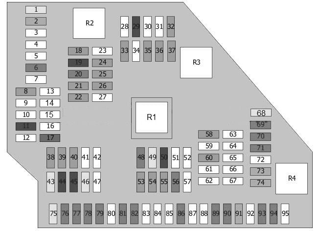
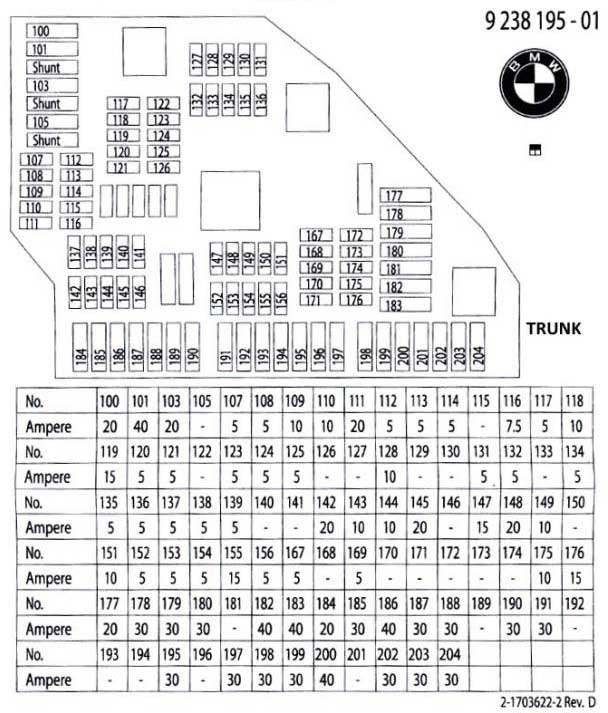
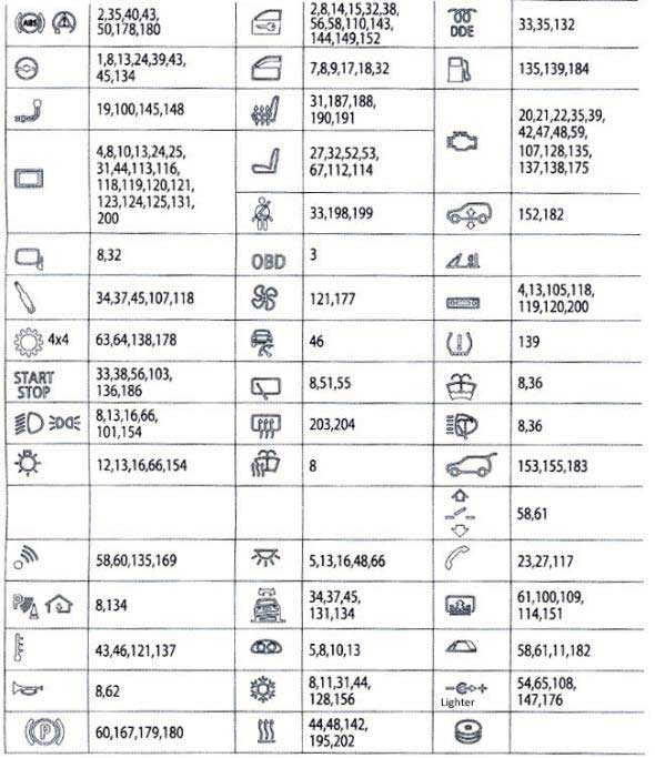
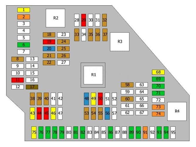
| Pozycja | Amperaż [A] | Chroniony obwód / funkcja |
|---|---|---|
| 1 | 20 | Trailer controller |
| 2 | 40 | FRM footwell module |
| 3 | – | Unused position |
| 4 | – | Unused position |
| 5 | – | Unused position |
| 6 | 30 | Hi-Fi amplifier / headset connector module, depending on equipment |
| 7 | – | Unused position |
| 8 | 5 | Charging management / DSC, depending on version |
| 9 | – | Unused position |
| 10 | – | Unused position |
| 11 | 10 | Soft Close automatic door closing |
| 12 | – | Unused position |
| 13 | – | Unused position |
| 14 | – | Unused position |
| 15 | – | Unused position |
| 16 | – | Unused position |
| 17 | 7.5 | Rear information display |
| 18 | 5 | Telematics and USB |
| 19 | 10 | Information display / rear entertainment |
| 20 | 15 | Headset connector module / audio equipment |
| 21 | 5 | Hi-Fi amplifier and DVD |
| 22 | 5 | Infotainment, video system and multimedia cooling fan |
| 23 | – | Unused position |
| 24 | 5 | Camera control module |
| 25 | 5 | Night Vision |
| 26 | 5 | Video system |
| 27 | – | Unused position |
| 28 | – | Unused position |
| 29 | 10 | Exhaust flap / wastegate control valve, depending on powertrain |
| 30 | – | Unused position |
| 31 | – | Unused position |
| 32 | 5 | Lane departure warning |
| 33 | 5 | Auxiliary heater or F07 roof equipment, depending on version |
| 34 | – | Unused position |
| 35 | 5 | Rear axle inclination sensor, PDC, Park Assist or Servotronic according to equipment |
| 36 | 5 | Electric changeover valve / exhaust flap |
| 37 | 5 | DC-DC converter or F07 roof controller |
| 38 | 5 | Cooling fan cut-off relay |
| 39 | 5 | xDrive transfer case |
| 40 | 5 | Fuel tank leak detection or tyre pressure monitoring |
| 41 | – | Unused position |
| 42 | – | Unused position |
| 43 | 20 | Auxiliary or parking heater |
| 44 | 10 | Soft Close automatic door closing |
| 45 | 10 | Soft Close automatic door closing |
| 46 | 20 | Trailer socket / terminal connector |
| 47 | – | Unused position |
| 48 | 15 / 20 | Additional 12 V outlet |
| 49 | 20 | F07 roof controller / towbar electronics, version dependent |
| 50 | 10 | Soft Close automatic door closing |
| 51 | – | Unused position |
| 52 | – | Unused position |
| 53 | 5 | Suspension height control |
| 54 | 5 | Remote boot lid release / tailgate switch |
| 55 | 5 | Luggage compartment lamp |
| 56 | 15 | Tailgate / boot lock |
| 57 | – | Unused position |
| 58 | 5 | Electric parking brake control unit |
| 59 | – | Unused position |
| 60 | 5 | Alarm system, emergency call and fuel system leak diagnostics |
| 61 | – | Unused position |
| 62 | – | Unused position |
| 63 | – | Unused position |
| 64 | – | Unused position |
| 65 | – | Unused position |
| 66 | – | Unused position |
| 67 | – | Unused position |
| 68 | 20 | Heater blower |
| 69 | 30 | xDrive transfer case, if equipped |
| 70 | 30 | Electric parking brake controller |
| 71 | 30 | Electric parking brake controller |
| 72 | – | Unused position |
| 73 | 40 | Air-conditioning compressor clutch relay or F07 roof system, depending on variant |
| 74 | 40 | Electric / remote tailgate opening |
| 75 | 20 | Fuel pump control module (EKPS) |
| 76 | 30 | Hi-Fi amplifier, if equipped |
| 77 | 30 | DC-DC converter |
| 78 | 30 | Rear seat adjustment / heating controller |
| 79 | 30 | Rear seat adjustment / heating controller |
| 80 | – | Unused position |
| 81 | 30 | Driver seat heating controller |
| 82 | 30 | Passenger seat heating controller |
| 83 | – | Unused position |
| 84 | – | Unused position |
| 85 | – | Unused position |
| 86 | 30 | Auxiliary heating |
| 87 | – | Unused position |
| 88 | – | Unused position |
| 89 | 30 | Seatbelt pretensioner controller, if fitted |
| 90 | 30 | Seatbelt pretensioner controller, if fitted |
| 91 | 40 | Hi-Fi amplifier |
| 92 | – | Unused position |
| 93 | 30 | Auxiliary heating |
| 94 | 30 | Heated rear window |
| 95 | – | Unused position |
| R1 | – | Terminal 30 relay |
| R2 | – | Terminal 30 relay |
| R3 | – | Terminal 15 relay |
| R4 | – | Heated rear-window relay |
In this arrangement the fuel pump controller (EKPS) is supplied by local rear position 75 (20 A). The rear 12 V outlet can use position 48 (15 / 20 A). The heated rear window is listed at local rear position 94 (30 A), alongside other relay-controlled circuits.
Additional fuse box beside an auxiliary battery
Some vehicles have an extra battery and a smaller, separately numbered fuse panel. The relevant positions protect the auxiliary battery controller, charging connections and selected audio equipment. If the additional battery is not fitted, the entire panel may be absent.
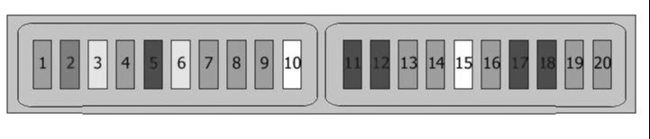
| Pozycja | Amperaż [A] | Chroniony obwód / funkcja |
|---|---|---|
| 1 | 5 | Auxiliary battery control module |
| 2 | – | Unused position |
| 3 | 20 | Auxiliary battery control module |
| 4 | 2 / 5 | Sound controller, version-dependent |
| 5 | 10 | Charging socket / connector |
| 6 | 15 / 20 | Sound controller |
| 7 | 5 | Unused or equipment-dependent circuit |
| 8 | 5 | Unused or equipment-dependent circuit |
| 9 | 5 | Auxiliary battery controller |
| 10 | – | Unused position |
| 11 | 10 | Charging socket / connector |
| 12 | 10 | Charging socket / connector, configuration dependent |
| 13 | 5 | Unused or equipment-dependent circuit |
| 14 | 5 | Switches |
| 15 | – | Unused position |
| 16 | 5 | Auxiliary battery controller |
| 17 | 10 | Unused or equipment-dependent circuit |
| 18 | 10 | Auxiliary battery controller |
| 19 | 5 | Auxiliary battery controller |
| 20 | 5 | Auxiliary battery controller |
Auxiliary rear relays and supply fuse
The supplementary relay panel is equipment dependent. The original article identifies R1-R5 and a 100 A supply link; the relay letters are not interchangeable with the relays shown on other body or equipment variants.
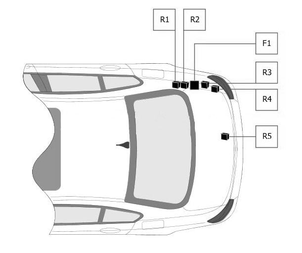
| Pozycja | Amperaż [A] | Chroniony obwód / funkcja |
|---|---|---|
| R1 | – | Alarm / indicator relay according to optional relay panel |
| R2 | – | Rear electric windows relay |
| R3 | – | Cut-off relay |
| R4 | – | Rear electric windows relay |
| R5 | – | Air-conditioning compressor clutch relay |
| F1 | 100 | Auxiliary luggage compartment fuse panel supply |
Battery positive-terminal high-current fuses
This block supplies large electrical loads and entire distribution branches. Its 50-250 A fusible links must never be bypassed or replaced using the procedure for ordinary blade fuses.
| Pozycja | Amperaż [A] | Chroniony obwód / funkcja |
|---|---|---|
| 1 | 100 | Cooling fan cut-off relay |
| 2 | 100 | Main DDE relay |
| 3 | 100 / 125 | Electromechanical power steering, cut-off relay or additional fuse box feed, depending on version |
| 4 | – | Unused position |
| 5 | – | Unused position |
| 6 | 50 | Hi-Fi amplifier |
| 7 | 60 | Vehicle level control / rear axle sensor, depending on version |
| 8 | 100 | Main luggage compartment fuse panel supply |
| 9 | 250 | Junction Box main supply |
| 10 | 100 / 150 | Luggage main fuse panel / electric power steering, depending on version |
Practical BMW F10/F11 fault checks
Cigarette lighter or 12 V socket not working: check glovebox fuse 54 (20 A), then variant-dependent fuse 65 and rear local position 48. Inspect the socket for metal objects and disconnect accessories before replacement.
Front wipers stopped: the documented glovebox assignment is F51 (30 A). Inspect the motor, mechanism and wiring if the correct fuse is intact.
Fuel pump not operating: check the documented local rear fuse 75 (20 A), then verify the EKPS module power supply and diagnostic trouble codes. Engine control feeds may be separate depending on powertrain.
Multiple DSC / stability faults: this installation uses several separate circuits, including glovebox fuse 2, 40 and 69, plus high-current feeds. Avoid replacing modules before checking their battery supplies and grounding.
Heated rear window not operating: check local rear fuse 94 (30 A) and the applicable relay arrangement. Blower not running: check glovebox fuse 68 (40 A) before diagnosing the fan regulator.
F10, F11, F07 and F18 differences: the F11 Touring has tailgate / rear wiper equipment, the F07 has a different rear lid, and xDrive and supplementary batteries add other circuits. Unoccupied slots are often factory-correct. Always replace a failed fuse with the original rated value.
See also BMW X3 F25 fuse box diagrams and BMW 1 Series F20/F21 fuse diagrams. Shared BMW electrical technology does not imply that fuse numbering is interchangeable.