
BMW 5 Series E39 (1996-2003) is the fourth-generation 5 Series, produced as a saloon and Touring estate. Its electrical distribution is spread across the engine bay, glove compartment, relay modules behind the glovebox, the passenger-side footwell and the right side of the luggage compartment. The E39 is not the later E60/E61 or F10 generation, which use different layouts.
This article preserves the full 140 fuse, relay and circuit rows in nine tables from the updated Polish technical guide. The E39 uses several different configurations for the March 1998 production change, the petrol and diesel engine families, and optional equipment such as rear air suspension, independent heating and the electric steering column. The fuse assignment card provided with the individual car takes priority over a different-year chart.
Where are the fuse boxes in a BMW E39?
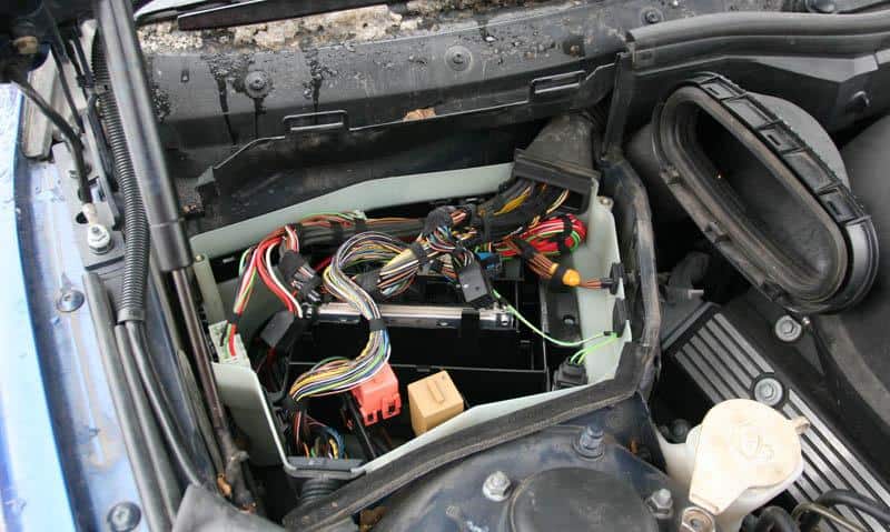
Engine electronics box: with the ignition switched off, open the bonnet and locate the covered E-box at the rear right side of the engine compartment near the bulkhead, as viewed in the factory vehicle orientation. Release the cover clips and inspect the electronics and relay carrier; Type 1 and Type 2 differ by engine and build date. Do not disturb engine control connectors with the system energised.
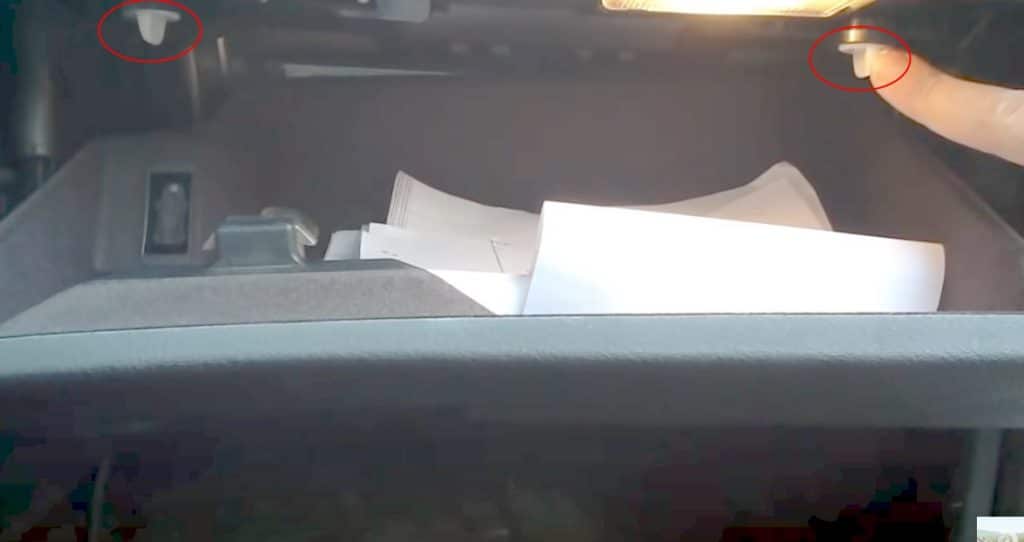
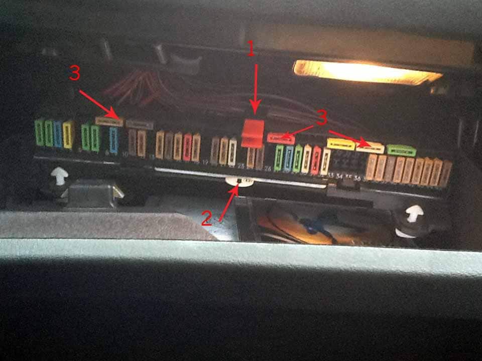
Glove compartment panel: open the passenger-side glovebox and turn its two white retaining knobs approximately a quarter-turn to release the main fuse panel, which folds downward. The car’s fuse legend and fuse puller are stored with the carrier. The numbered main panel is F1-F45; this is the first place to check for lights, cabin electronics and many accessories.
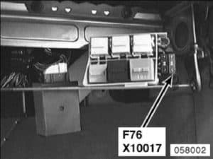
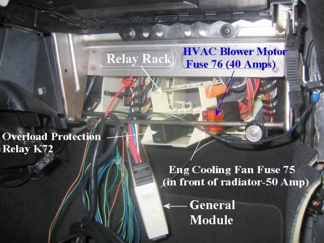
Behind the glovebox: the additional relay holder, including F75 and F76, requires more trim clearance and sometimes partial glovebox removal. Passenger footwell: high-current fuses F107-F114 are below the right-side floor trim/carpet and are not normally accessible for routine fuse replacement.
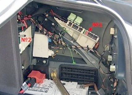
Luggage compartment: open the boot and release the right-hand side trim cover to expose the secondary fuse/relay block F46-F74. The larger F100-F106 power distribution links are adjacent to the battery. Use the manufacturer’s battery-isolation procedure before inspecting bolted high-current connections.
Engine compartment electronics – Type 1
Type 1 has separate engine and transmission control units and dedicated wiper, air-conditioning fan and ABS relays. The 9-row list uses physical positions on this particular arrangement. The original illustrated module is not a fuse card for a different E-box configuration.
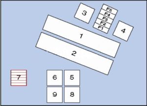
| Pozycja | Amperaż [A] | Chroniony obwód / funkcja |
|---|---|---|
| 1 | – | Engine Control Module (ECM) |
| 2 | – | Transmission Control Module (TCM) |
| 3 | – | Engine control electronics fuse or electrical feed |
| 4 | – | Engine management relay |
| 5 | – | Windscreen wiper motor relay I |
| 6 | – | Windscreen wiper motor relay II |
| 7 | – | Air-conditioning condenser fan relay I |
| 8 | – | Air-conditioning condenser fan relay III |
| 9 | – | Anti-lock braking system (ABS) relay |
Engine compartment electronics – Type 2
This arrangement has nine engine relays/modules and five normal fuses for engine management. F1-F5 are specific to this engine-bay electronics box and must not be confused with F1-F5 in the glove compartment. Different engine types use different coil, secondary air pump and oxygen sensor supplies.
| Pozycja | Amperaż [A] | Chroniony obwód / funkcja |
|---|---|---|
| 1 | – | Engine Control Module (ECM) |
| 2 | – | Automatic transmission control module (TCM) |
| 3 | – | Engine management system relay |
| 4 | – | Ignition coil relay; not installed on some 520i, 525i and 530i versions |
| 5 | – | Front windscreen wiper motor relay 1 |
| 6 | – | Front windscreen wiper motor relay 2 |
| 7 | – | Air conditioning condenser fan relay 1, selected models built up to March 1998 |
| 8 | – | Air conditioning condenser fan relay 3, selected models built up to March 1998 |
| 9 | – | Secondary Air Injection (AIR) pump relay |
| F1 | 30 | ECM, EVAP tank-purge valve, mass air flow sensor, camshaft position sensor; mapped thermostat on some 535i/540i engines |
| F2 | 30 | Secondary air pump, variable intake components, injectors and engine controller, depending on engine |
| F3 | 20 | Crankshaft position sensor, camshaft position sensors and mass air flow (MAF) sensor |
| F4 | 30 | Heated exhaust oxygen sensors and automatic transmission TCM |
| F5 | 30 | Ignition coil relay, except some 520i, 525i and 530i variants |
Main glove compartment fuses F1-F45 – from March 1998
The main cabin panel includes wipers, headlights, horn, radio and navigation electronics, fuel pump relay supplies, seat adjustment, SRS, ABS and body control. Some ratings differ by date or equipment. For example, F5 can be 20 A or 30 A for the sunroof and F7 may be used for the front cigarette lighter on later cars.
| Pozycja | Amperaż [A] | Chroniony obwód / funkcja |
|---|---|---|
| F1 | 30 | Windscreen wiper motor relay |
| F2 | 30 | Headlamp washers |
| F3 | 15 | Horn |
| F4 | 20 | Multifunction body control module |
| F5 | 20 / 30 | Sunroof, 20 A or 30 A according to equipment |
| F6 | 30 | Passenger-side electric door mirror |
| F7 | 20 / 30 | Selected later vehicles: front cigarette lighter or 12 V socket, equipment and production-dependent |
| F8 | – | Unoccupied position |
| F9 | 15 | Heating and air conditioning controller |
| F10 | 30 | Passenger electric seat adjustment |
| F11 | 7.5 | Multifunction module and Servotronic speed-sensitive steering |
| F12 | 5 | Immobiliser |
| F13 | 30 | Driver electric seat and powered steering column adjustment |
| F14 | 5 | Engine Control Module (ECM) |
| F15 | 7.5 | Automatic transmission TCM, engine oil level sensor, alternator; electronics-box temperature switch on 530d |
| F16 | 5 | Exterior light control module |
| F17 | 10 | Fuel pump relay, ABS controller and switch assembly |
| F18 | 5 | Instrument cluster |
| F19 | 5 | Overvoltage protection relay 2 |
| F20 | 5 / 7.5 | Heating and A/C controller, rear window heater relay and tyre-pressure monitoring |
| F21 | 5 | Cigarette lighter relay, seat/steering adjustment relay, HomeLink, parking sensors and self-dimming mirror |
| F22 | 25 | Fuel pump relay on selected 530d, 520i, 525i and 530i |
| F23 | 7.5 | Rear multifunction display, if fitted |
| F24 | 5 | Instrument panel, tyre-pressure monitoring and steering angle sensor |
| F25 | 7.5 | Multifunction information display |
| F26 | – | Unoccupied position |
| F27 | 30 | Multifunction body control module |
| F28 | 15 | Automatic transmission |
| F29 | 30 | Driver door functions control module |
| F30 | 25 | ABS module |
| F31 | 10 | Fuel pump and ABS relays; on petrol engines, secondary air pump relay |
| F32 | 25 | Switch block and equipment-dependent electrical consumers |
| F33 | – | Unoccupied position |
| F34 | 10 | Multifunction steering wheel, driver airbag and heated steering wheel |
| F35 | 5 | Rear air conditioning fan, if fitted |
| F36 | – | Unoccupied position |
| F37 | 5 | Immobiliser control module |
| F38 | 5 | Multifunction module, horn relay, rain sensor, automatic gear selector lock and OBD diagnostics |
| F39 | 7.5 | Vanity mirror lamps and rechargeable glovebox torch |
| F40 | 5 | Instrument cluster, seat controller, airbag crash sensor and driver’s seat belt buckle switch |
| F41 | 5 | Lighting module and clutch pedal / brake pedal switches |
| F42 | 5 | Supplemental Restraint System (SRS) airbag module |
| F43 | 5 | Overvoltage protection relay 1 |
| F44 | 5 | Multifunction steering wheel, driver airbag and multifunction displays |
| F45 | 7.5 | Multi-switch assembly, depending on trim and engine |
Differences on cars made before March 1998
Two important fuse-card differences are shown separately below. On older cars, F7 may supply the A/C condenser fan relay rather than the front 12 V outlet, while F22 can supply another condenser fan relay instead of the fuel pump relay used on certain later engines. Treat both amperage and function as build-specific.
| Pozycja | Amperaż [A] | Chroniony obwód / funkcja |
|---|---|---|
| F7 | 20 / 30 | Before March 1998: F7 20/30 A condenser cooling fan relay 1; on some later cars, the same fuse number feeds the front cigarette lighter or socket |
| F22 | 25 / 30 | Before March 1998: F22 30 A condenser fan relay 2; on some later engines, F22 is 25 A for the fuel pump relay |
Relay block behind the glove compartment and F75/F76
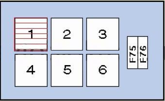
A second unit behind the glove compartment contains relays for the cooling fan, starter, headlamp washers, power seats and heater blower. The independent high-current fuses F75 and F76 feed the cooling and heating ventilation circuits. The relay positions themselves have no blade-fuse amperage.
| Pozycja | Amperaż [A] | Chroniony obwód / funkcja |
|---|---|---|
| 1 | – | Air conditioning condenser fan relay 2 on cars made before March 1998 |
| 2 | – | Headlamp washer pump relay |
| 3 | – | Unoccupied relay position |
| 4 | – | Starter relay |
| 5 | – | Power seat and adjustable steering-column relay |
| 6 | – | Heater and ventilation blower relay |
| F75 | 50 | F75: high-current cooling fan or A/C condenser blower supply |
| F76 | 40 | F76: air conditioning / heater blower control module main supply |
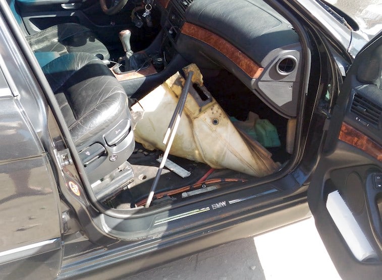
High-current fuses F107-F114 under the right-side floor
These eight links distribute 50-80 A supplies for engine/ABS electronics, dashboard circuits, ignition, steering column adjustment and exterior lighting. They can protect entire branches of the vehicle. A failed main fuse often indicates a larger fault; use proper battery isolation and electrical testing rather than replacing it blindly.
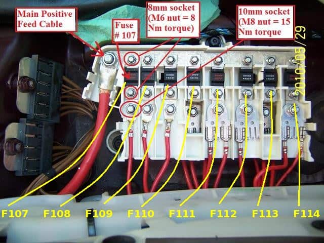
| Pozycja | Amperaż [A] | Chroniony obwód / funkcja |
|---|---|---|
| F107 | 50 | Secondary Air Injection (AIR) pump relay supply |
| F108 | 50 | Anti-lock braking system (ABS) controller power supply |
| F109 | 80 | Engine management relay and engine-bay electrical box F4/F5 |
| F110 | 80 | Power to parts of main glovebox fuse box F1-F12 and F22-F25 |
| F111 | 50 | Ignition switch main feed |
| F112 | 80 | Exterior light control module |
| F113 | 80 | Seat adjustment, steering-column adjustment, F27-F30 and F76 plus seat electronics |
| F114 | 50 | Ignition switch and on-board diagnostic (DLC) supply |
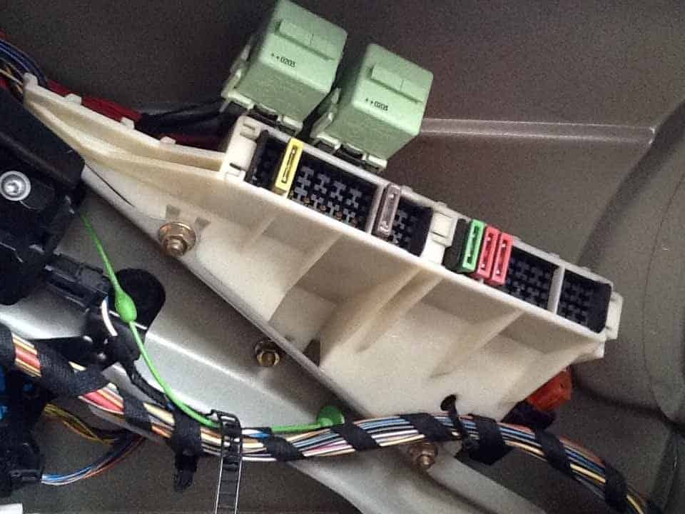
Luggage compartment fuse and relay box – Type 1
Open the right-side boot trim to find the secondary electrical distribution. On the Type 1 card, F51 (30 A) may supply the rear cigarette lighter or rear accessory socket, and F52 (30 A) the front cigarette lighter relay. F54 (15 A) is the fuel pump supply. Several tailgate and rear suspension circuits are fitted only on Touring or equipped cars.
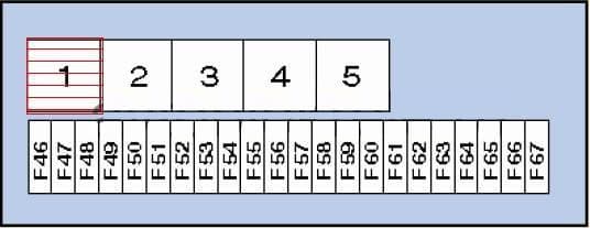
| Pozycja | Amperaż [A] | Chroniony obwód / funkcja |
|---|---|---|
| 1 | – | Overvoltage protection relay 1 |
| 2 | – | Fuel pump relay |
| 3 | – | Heated rear-window relay |
| 4 | – | Overvoltage protection relay 2 |
| 5 | – | Fuel filler flap actuator relay |
| F46 | – | Unoccupied position |
| F47 | 15 / 20 | Auxiliary or independent heating system |
| F48 | 5 | Self-dimming mirror, alarm system, tilt/motion sensor and alarm siren |
| F49 | 30 | Rear air suspension compressor relay |
| F50 | 7.5 | Rear air suspension controller, if fitted |
| F51 | 30 | Rear cigarette lighter / rear accessory socket |
| F52 | 30 | Front cigarette lighter relay and front 12 V outlet |
| F53 | 5 | Antenna amplifier, boot/tailgate lock on the Touring |
| F54 | 15 | Fuel pump relay |
| F55 | 20 | Rear wiper/washer relay |
| F56 | 30 | Radio, navigation, audio amplifier, CD changer and onboard monitor |
| F57 | 10 | Mobile telephone |
| F58 | 10 | Overvoltage protection relay 1 |
| F59 | 20 | Trailer electrical socket |
| F60 | 15 | Suspension controller or related switch assembly |
| F61 | 25 | Rear seat heating, left and right sides |
| F62-F65 | – | Unoccupied fuse positions F62-F65 |
| F66 | 40 | Heated rear window relay |
| F67 | – | Unoccupied position F67 |
Luggage compartment fuse box – Type 2
The alternate card gives a different distribution of vacant positions and accessory circuits. In particular, F51 is unused in this version while F52 (30 A) serves the cigarette lighter. F46/F47 supply independent heating; rear suspension and telephone supplies depend on equipment. Use the label physically present in the car.
| Pozycja | Amperaż [A] | Chroniony obwód / funkcja |
|---|---|---|
| 1 | – | Main ignition circuits relay |
| 2 | – | Fuel pump relay |
| 3 | – | Heated rear window relay |
| 4 | – | Auxiliary ignition circuit relay |
| 5 | – | Parking/independent heating system relay |
| F46 | 15 | Auxiliary heating or independent ventilation |
| F47 | 15 | Independent heating system |
| F48 | 5 | Anti-theft alarm system |
| F49 | 30 | Rear axle air suspension control |
| F50 | 7.5 | Rear axle air suspension control |
| F51 | – | Unoccupied position F51 on this configuration |
| F52 | 30 | Front cigarette lighter or accessory socket |
| F53 | 7.5 | Central locking system |
| F54 | 15 | Fuel pump |
| F55 | – | Unoccupied position F55 |
| F56 | 30 | Radio, navigation and onboard computer monitor |
| F57 | 10 | Mobile telephone |
| F58 | 10 | Audio, onboard monitor, navigation and telephone systems |
| F59 | – | Unoccupied position F59 |
| F60 | 15 | Self-levelling suspension control |
| F61-F65 | – | Unoccupied positions F61-F65 |
| F66 | 40 | Heated rear window |
| F67-F74 | – | Unoccupied positions F67-F74 in typical configuration |
Main high-current fuses F100-F106 near the battery
The trunk-mounted main power block feeds the footwell distributor, the individual luggage fuses, trailer electronics and the supplementary heater. F100 is a 200 A link and F105 a 100 A link on the documented chart. These are bolted, high-energy fuses and should only be serviced under appropriate isolation procedures.
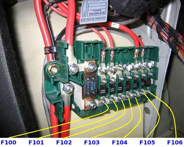
| Pozycja | Amperaż [A] | Chroniony obwód / funkcja |
|---|---|---|
| F100 | 200 | High-current supply to the F107-F114 passenger footwell fuse panel |
| F101 | 80 | Supply to luggage compartment fuses F46-F50 and F66 |
| F102 | 80 | Supply to luggage compartment fuses F51-F55 |
| F103 | 50 | Trailer control module |
| F104 | 50 | Overvoltage protection relay 2 |
| F105 | 100 | Supply to F75 and auxiliary independent heater |
| F106 | 80 | Power distribution to luggage compartment F56-F59 |
BMW E39 – useful electrical fault checks
Front 12 V outlet or cigarette lighter stopped: start by identifying the car’s fuse card. F52 (30 A) is a frequent supply in the luggage compartment; F7 (20/30 A) is an alternative on some later glovebox cards, and F21 (5 A) can control the lighter relay. A rear outlet may use F51 (30 A) in Type 1 installations. Do not assume all three positions are occupied.
Fuel pump receives no power: inspect F54 (15 A) and the fuel pump relay in the luggage compartment. Depending on engine, F17, F22 or F31 in the glovebox may protect related controls. Measure voltage at the pump before replacing it.
Heater blower not operating: inspect the relevant F76 (40 A) behind the glovebox and its relay, then the blower final-stage module. Rear self-levelling suspension warning: check F49 (30 A), F50 (7.5 A), the air compressor relay and ride-height sensors if the car is equipped with rear air suspension.
Several unrelated electrical consumers fail together: check the relevant F100-F114 main distributors, ignition switch and battery connections. Failure of a 50-200 A link can remove power from an entire group; do not bypass it with wire or fit a higher rating.
For a later 5 Series platform, see the BMW 5 Series F10/F11/F07/F18 fuse and relay diagrams. Its numbered sockets are different and should not be used to identify an E39 circuit.