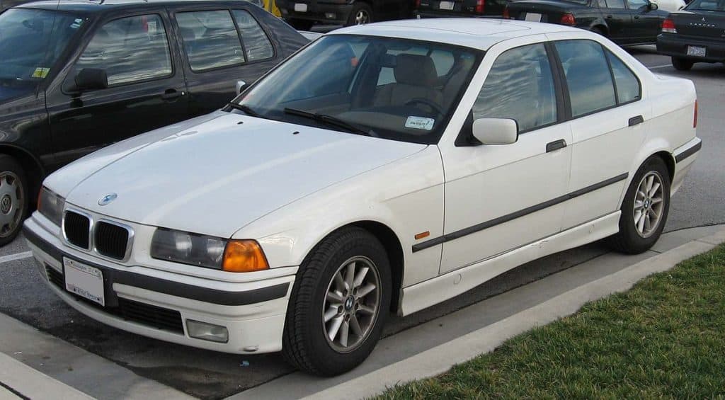
BMW 3 Series E36 and E36/5 Compact (1990-2000) use a front fuse and relay panel in the engine bay, additional fuse and relay holders beneath the dashboard and equipment-dependent protection in the luggage compartment. The 316i, 318i, 318is, 318ti, 320i, 323i, 325i, 328i, 318tds, 325tds and M3 vary by engine, production date, country and saloon, Touring, Coupe, Compact or Convertible body.
These nine tables preserve all 282 equipment and variant rows from the Polish original, including every alternative relay assignment, optional position and differing amperage. They retain five original model-specific illustrations. The detailed 1998 BMW electrical troubleshooting manual confirms supplemental F47-F50 and Sequential M Gearbox F111/F222 allocations; those must not be assumed present in every early E36.
Where are the BMW E36 fuse and relay boxes?
Main front box: with ignition and electrical consumers off, open the bonnet and find the rectangular black cover on the left side of the engine compartment near the strut tower. Release the lid clips without pulling the adjoining wiring, then compare the underside legend with the 46 numbered fuse cavities and R1-R15 relays. Different engines use different auxiliary relay assignments.
Passenger compartment supplementary holders: remove the relevant lower dashboard trim to reach additional relays and connecting strips. The relay carrier and connector strip 1 are beneath the left portion of the dashboard on typical left-hand-drive cars; connector strip 2 sits beneath the right side. Do not pull modules from their wiring and do not disturb the airbag/SRS harness. Some cars have additional F47, F48 and F50 protection in these carriers.
Convertible and SMG auxiliary protection: the Convertible has a separate F49 (20 A) soft-top fuse behind appropriate luggage-compartment trim. The M3 SMG installation can have an auxiliary box with F111 (25 A) for the hydraulic pump relay and F222 (7.5 A) for the SMG controller. The source does not provide verified physical diagrams for those two secondary holders, so no other-generation drawing has been substituted.

Front engine fuse panel F1-F46 – all 200 equipment rows
One physical fuse number can cover several components or alternative year-specific installations, so each source assignment is retained as its own table line. F32 (30 A) feeds the cigarette lighter and reading lamp relay. F18 (15 A) feeds the petrol fuel pump. F11 and F12 protect left and right dipped beams, and F29/F30 protect the high beams in the shown equipment version.
Model-year differences matter: F2 can be 15 A for trailer coupling or 5 A for engine control; F6 uses 20/30 A rear demister protection; F15 has 15/7.5 A front fog light variants; F17 uses 10/7.5 A depending on CCM, and F26 changes from 15 A early to 10 A after September 1992. Never install the higher alternative without checking the car’s fuse card.

| Pozycja | Amperaż [A] | Chroniony obwód / funkcja |
|---|---|---|
| 1 | 30 | Electric tilt/slide sunroof (SHD) |
| 2 | 15 | From September 1993: trailer coupling |
| 2 | 5 | From September 1996: engine management control system |
| 3 | 30 | Rear intermittent wipe/wash control unit on Touring and Compact |
| 3 | 30 | Headlamp washer system SRA |
| 3 | 30 | Radio and hi-fi audio supply, September 1994 to August 1995 |
| 4 | 15 | Terminal 15 load-reduction relay for seat heating |
| 5 | 30 | Front passenger electric seat adjustment switch |
| 6 | 20 | Rear window demister relay, 20 A variant |
| 6 | 30 | Rear window demister relay, 30 A variant |
| 7 | 5 | Electronic gear position indicator |
| 7 | 5 | Central door locking switch |
| 7 | 5 | Driver door locking switch |
| 7 | 5 | Driver door central locking actuator |
| 7 | 5 | ZVM central locking control module |
| 7 | 5 | Passenger door central locking actuator |
| 7 | 5 | Passenger door lock switch |
| 7 | 5 | Remote central locking control unit |
| 7 | 5 | Boot lid locking relay |
| 7 | 5 | Tailgate central locking on Touring |
| 7 | 5 | Convertible roof flap microswitch |
| 7 | 5 | Convertible top storage lid lock |
| 7 | 5 | Convertible soft top control module |
| 7 | 5 | Alpine alarm and anti-theft controller |
| 8 | 15 | Horn relay |
| 8 | 15 | Alpine anti-theft control module |
| 9 | 20 | Radio receiver |
| 9 | 20 | Hi-Fi amplifier |
| 9 | 20 | Subwoofer audio speaker |
| 9 | 20 | CD changer through August 1993 |
| 9 | 20 | Terminal R electrical load-shedding relay through August 1992 |
| 10 | 30 | ABS control electronics |
| 10 | 30 | Automatic Stability Control ASC electronics |
| 11 | 7.5 | Without check-control module CCM: left dipped-beam headlamp |
| 11 | 7.5 | With CCM: Check Control warning module |
| 12 | 7.5 | Without CCM: right dipped-beam headlamp |
| 12 | 7.5 | With CCM: Check Control module |
| 13 | 5 | Comfort relay on two-door cars |
| 14 | 30 | Driver-side electric window module through August 1993 |
| 14 | 30 | Passenger-side electric window module through August 1993 |
| 14 | 30 | Central body electronics ZKE IV from September 1993 |
| 15 | 15 | Left front fog lamp, 15 A configuration |
| 15 | 15 | Right front fog lamp, 15 A configuration |
| 15 | 15 | Instrument cluster, 15 A configuration |
| 15 | 7.5 | Left front fog lamp, alternate 7.5 A configuration |
| 15 | 7.5 | Right front fog lamp, alternate 7.5 A configuration |
| 15 | 7.5 | Instrument cluster, alternate 7.5 A configuration |
| 16 | 5 | Air-conditioning compressor relay |
| 16 | 5 | Auxiliary cooling fan low-speed relay |
| 16 | 5 | Auxiliary cooling fan high-speed relay |
| 17 | 10 | Without CCM: rear fog lamp switch, 10 A |
| 17 | 7.5 | With CCM: rear fog lamp switch, 7.5 A |
| 18 | 15 | Fuel pump electrical supply |
| 19 | 15 | Until August 1992: parking heating/ventilation relay box |
| 19 | 30 | From August 1993: heating auxiliary relay module, 30 A |
| 20 | 30 | Until August 1992: heater blower speed switch |
| 20 | 30 | From September 1992: |
| 20 | 30 | Without independent parked ventilation: heater blower relay |
| 20 | 30 | With independent parked ventilation: |
| 20 | 30 | Heater blower relay |
| 20 | 30 | Independent ventilation relay |
| 21 | 5 | ABS electrical controls |
| 21 | 5 | Automatic Stability Control ASC system |
| 22 | 5 | Main lighting switch |
| 22 | 5 | Daytime Running Lights coding diode |
| 23 | 5 | Turn signal and headlamp stalk switch |
| 23 | 5 | Instrument cluster |
| 23 | 5 | Thermal switch, Japanese-market equipment |
| 23 | 5 | ABS control module |
| 23 | 5 | Rear windscreen demister relay |
| 23 | 5 | Multifunction clock, display and onboard computer |
| 23 | 5 | Terminal 15 electrical load reduction relay |
| 23 | 5 | With IHKA automatic climate control: |
| 23 | 5 | With conventional heater control: |
| 23 | 5 | Heater coolant control valves |
| 23 | 5 | Heater temperature controller |
| 24 | 10 | Thermal switch for heated washer jets |
| 24 | 10 | Convertible rollover sensor |
| 24 | 10 | Exterior mirror control module |
| 24 | 10 | Parking Distance Control PDC module |
| 25 | 5 | Lighting switch |
| 25 | 5 | Daytime running light module from September 1997 |
| 25 | 5 | High-beam headlamp relay, September 1994 to August 1997 |
| 25 | 5 | Low-beam headlamp relay, September 1992 to August 1994 |
| 25 | 5 | Left position lamp relay, September 1993 to August 1994 |
| 25 | 5 | Right position/number plate lamp relay, September 1993 to August 1994 |
| 26 | 15 | Before September 1992, 15 A version: |
| 26 | 15 | Automatic gearbox program switch |
| 26 | 15 | Auxiliary electrical connector, US specification |
| 26 | 15 | Automatic transmission range selector switch |
| 26 | 15 | Diagnostic connector |
| 26 | 15 | Reverse-light switch without EGS |
| 26 | 10 | From September 1992, 10 A version: |
| 26 | 10 | Automatic gearbox range selector switch |
| 26 | 10 | Automatic gearbox mode switch |
| 26 | 10 | Diesel fuel heater circuit |
| 26 | 10 | Diesel alternator cut-out relay |
| 26 | 10 | Diagnostic connector |
| 26 | 10 | Thermal engine oil level switch |
| 26 | 10 | Oxygen sensor and secondary air pump relays |
| 26 | 10 | Reverse-light switch |
| 26 | 10 | SMG transmission control unit |
| 26 | 10 | Hydraulic pump relay |
| 26 | 10 | SMG hydraulic control unit |
| 26 | 10 | Starter immobilisation relay |
| 26 | 10 | Throttle body flap heater |
| 27 | 5 | Instrument cluster |
| 28 | 5 | With automatic gearbox EGS: range selector switch |
| 28 | 5 | With sequential manual gearbox SMG: |
| 28 | 5 | SMG control module |
| 28 | 5 | Electronic gear position indicator |
| 28 | 5 | Centre console gear position display |
| 29 | 7.5 | Left high-beam headlamp |
| 30 | 7.5 | Right high-beam headlamp |
| 31 | 5 | Instrument cluster |
| 31 | 5 | On-board display and multifunction clock |
| 31 | 5 | On-board computer |
| 31 | 5 | Analogue clock |
| 31 | 5 | Chime warning control module |
| 31 | 5 | EWS II immobiliser control unit from September 1994 |
| 31 | 5 | DWA alarm status LED |
| 31 | 5 | With IHKA automatic air conditioning: |
| 31 | 5 | Heater coolant control valves |
| 31 | 5 | Automatic climate control module |
| 31 | 5 | With IHKR semi-automatic heater controls: |
| 31 | 5 | IHKR climate control panel |
| 31 | 5 | Integrated climate regulation controller |
| 32 | 30 | Front cigarette lighter / 12 V outlet |
| 32 | 30 | Reading lamp relay |
| 33 | 10 | Ignition switch from September 1993 |
| 33 | 10 | Vehicle charging socket |
| 33 | 10 | Main lighting switch |
| 33 | 10 | CD changer from September 1993 |
| 33 | 10 | Cellular telephone |
| 33 | 10 | Door lock heating relay |
| 33 | 10 | Luggage compartment lamp |
| 33 | 10 | Central rear interior light on Touring |
| 33 | 10 | Right luggage compartment lamp on Compact |
| 33 | 10 | Right rear interior light with reading function |
| 33 | 10 | Left rear interior light with reading function |
| 33 | 10 | Front courtesy and reading lamps with ZKE |
| 33 | 10 | ZKE control unit from September 1993 |
| 33 | 10 | Front driver and passenger footwell lights |
| 33 | 10 | Left parking light relay |
| 33 | 10 | Driver-side power window module through August 1993 |
| 34 | 15 | Hazard warning flasher relay |
| 34 | 15 | Crash-alarm sensor where equipped |
| 35 | 25 | With ZVM: central locking module |
| 35 | 25 | With ZKE: central body electronics module |
| 36 | 30 | Front windscreen wipe/wash control module |
| 37 | 10 | Main lighting switch |
| 37 | 10 | Right parking and number plate light relay |
| 38 | 30 | ABS hydraulic and electronic controller |
| 38 | 30 | Automatic Stability Control ASC |
| 39 | 7.5 | Air-conditioning compressor relay |
| 40 | 30 | Driver’s seat adjustment switch |
| 40 | 30 | Driver lumbar support control switch |
| 41 | 30 | Auxiliary fan first stage relay, low speed, diesel only |
| 41 | 30 | Auxiliary fan second stage relay, high speed |
| 42 | 7.5 | Electronic seat monitoring controller |
| 42 | 7.5 | Driver side impact airbag sensor |
| 42 | 7.5 | Passenger side impact airbag sensor |
| 42 | 7.5 | Convertible rollover sensor |
| 42 | 7.5 | SRS airbag diagnostic module |
| 42 | 7.5 | Driver seat belt buckle switch |
| 43 | 5 | Right rear interior lamp |
| 43 | 5 | Left rear interior lamp |
| 43 | 5 | Upper Hi-Fi sound switch |
| 43 | 5 | ZVM central locking module |
| 43 | 5 | ZKE central body electronics controller |
| 43 | 5 | Surround-sound switching relay |
| 43 | 5 | Passenger vanity mirror illumination |
| 43 | 5 | Driver vanity mirror illumination |
| 43 | 5 | Front courtesy and reading lamp |
| 43 | 5 | Convertible soft-top control unit |
| 43 | 5 | Remote central locking control module |
| 43 | 5 | Cellular telephone |
| 43 | 5 | Reading lamp relay |
| 43 | 5 | Alpine anti-theft alarm control |
| 44 | 15 | Windscreen wash/wipe control module Low II |
| 44 | 15 | Windscreen wash/wipe module |
| 44 | 15 | Rear intermittent wipe/wash controller, Touring/Compact |
| 44 | 15 | Rear wiper stalk switch on Touring/Compact |
| 44 | 15 | Radio/audio supply |
| 44 | 15 | Glovebox light switch and lamp |
| 44 | 15 | Dual relay module through August 1995 |
| 44 | 15 | Terminal R load-shedding relay through August 1992 |
| 45 | 7.5 | Check Control Module CCM |
| 45 | 7.5 | Immobiliser EWS II transceiver from September 1995 |
| 45 | 7.5 | Starter immobilisation switch from September 1996 |
| 45 | 7.5 | On-board computer / multifunction clock / display |
| 45 | 7.5 | Wiper control relay through August 1995 |
| 45 | 7.5 | Wiper motor relay through August 1995 |
| 46 | 15 | Clutch pedal switch |
| 46 | 15 | Instrument cluster |
| 46 | 15 | Brake-light switch |
| 46 | 15 | Cruise control module |
| 46 | 15 | Cruise control switch |
| 46 | 15 | Diagnostic data-link connector from September 1995 |
| 46 | 15 | Low-level onboard computer BC-low |
Front power distribution relay positions R1-R15
Depending on the engine, these relays can control the fuel pump, engine ECU, diesel alternator cut-out, secondary-air pump, oxygen sensor, horn, fog lights, main/dipped beams, hazard flasher, cabin blower, rear window demister, ABS pump and cooling fans. The separate “Or” rows in the table are equipment alternatives for one socket, not several relays fitted simultaneously. R6 and R7 can exchange main/dipped beam roles around September 1993.
| Pozycja | Amperaż [A] | Chroniony obwód / funkcja |
|---|---|---|
| R1 | – | Fuel pump relay |
| R1 | – | Or, depending on engine/equipment |
| R1 | – | Oxygen-sensor heater and air-pump relays on M3 |
| R1 | – | Or, depending on engine/equipment |
| R1 | – | Secondary air injection pump relay |
| R1 | – | Or, depending on engine/equipment |
| R1 | – | Engine management ECU main relay |
| R1 | – | Or, depending on engine/equipment |
| R1 | – | Diesel alternator cut-out relay |
| R2 | – | Engine management control relay |
| R2 | – | Or, depending on engine/equipment |
| R2 | – | Fuel pump relay |
| R3 | – | Oxygen sensor heater relay |
| R3 | – | Or, depending on engine/equipment |
| R3 | – | Electric fuel pump / start sensor relay, as described in archived source |
| R3 | – | Or, depending on engine/equipment |
| R3 | – | Wiper motor relay |
| R3 | – | Or, depending on engine/equipment |
| R3 | – | Engine management ECU relay |
| R3 | – | Or, depending on engine/equipment |
| R3 | – | Secondary-air injection pump relay |
| R3 | – | Or, depending on engine/equipment |
| R3 | – | Diesel fuel supply pump relay |
| R4 | – | Horn relay |
| R5 | – | Front fog-light relay |
| R6 | – | High-beam relay through August 1993 |
| R6 | – | Or, depending on year |
| R6 | – | Low-beam relay from September 1993 |
| R7 | – | Low-beam relay through August 1993 |
| R7 | – | Or, depending on year |
| R7 | – | High-beam relay from September 1993 |
| R7 | – | Or, depending on engine |
| R7 | – | Secondary-air injection pump relay |
| R8 | – | Hazard warning flasher relay |
| R9 | – | Cabin ventilation blower relay |
| R10 | – | Heated rear-window demister relay |
| R11 | – | ABS electronics relay |
| R12 | – | ABS hydraulic pump motor relay |
| R12 | – | Or, depending on ABS system |
| R12 | – | Time-delayed ABS pump motor relay |
| R13 | – | Auxiliary cooling fan high-speed relay, stage 2 |
| R14 | – | Air-conditioning compressor relay |
| R15 | – | Auxiliary cooling fan low-speed relay, stage 1 |
Supplementary left dash fuses F48 and F50
F48 (40 A) feeds the auxiliary radiator cooling fan high-speed relay and F50 (5 A) supplies exhaust flap and carbon-canister valves on applicable petrol engines. These positions are outside the regular F1-F46 main engine fuse bank and are not equipped on every model.

| Pozycja | Amperaż [A] | Chroniony obwód / funkcja |
|---|---|---|
| 48 | 40 | Auxiliary cooling fan high-speed stage 2 relay |
| 50 | 5 | Exhaust-gas flap valve |
| 50 | 5 | Evaporative emissions carbon canister valve |
Supplementary relay carrier beneath left dashboard
The left-hand carrier can contain independent parked ventilation, dual equipment relay, alarm sensor, headlamp cleaning or DRL, comfort sunroof electronics and early terminal R load reduction. Alternatives for the same local relay position remain separate, as listed in the Polish source.
| Pozycja | Amperaż [A] | Chroniony obwód / funkcja |
|---|---|---|
| R1 | – | Independent parked ventilation relay |
| R2 | – | Dual-purpose relay, through August 1995 |
| R3 | – | Failure alarm monitoring sensor |
| R4 | – | Headlamp/fog lamp cleaning module SRA through August 1995 |
| R4 | – | Or, depending on equipment |
| R4 | – | High-beam headlamp relay |
| R4 | – | Or, depending on equipment |
| R4 | – | Daytime running light relay |
| R5 | – | Comfort electronics relay |
| R5 | – | Or, depending on equipment |
| R5 | – | Tilt/slide sunroof comfort relay |
| R6 | – | Terminal R electrical load-shedding relay through August 1992 |
Left connector strip 1 – F47 and local relays
F47 (15 A) protects the Alpine alarm horn, onboard computer and anti-theft control on versions with that equipment. The same connector strip supports local relays for terminal 15 load shedding, Compact horn, rear lights, wipers, rear hinged windows, starter and starter interlock. Do not confuse its local R1-R4 with the main engine relay R1-R15.

| Pozycja | Amperaż [A] | Chroniony obwód / funkcja |
|---|---|---|
| 47 | 15 | Alpine anti-theft horn relay |
| 47 | 15 | On-board computer |
| 47 | 15 | Alpine security and anti-theft module |
| Pozycja | Amperaż [A] | Chroniony obwód / funkcja |
|---|---|---|
| R1 | – | Terminal 15 load-reduction relay |
| R1 | – | Or, depending on model |
| R1 | – | Horn relay on Compact |
| R2 | – | Rear tail-lamp relay |
| R2 | – | Or, depending on model |
| R2 | – | Wiper relay through August 1995 |
| R3 | – | Wiper motor relay through August 1995 |
| R4 | – | Hinged rear quarter-window relay |
| R4 | – | Or, depending on model |
| R4 | – | Starter motor relay through August 1994 |
| R4 | – | Or, depending on model |
| R4 | – | Starter immobilisation relay from September 1993 to September 1994 |
Right connector strip 2 – relay positions
The right-hand relay strip contains lighting relays, door lock heating and rear window blower controls. Relay R2 may be left position lamps or a Japanese market thermal switch depending on vehicle wiring. A right-hand-drive vehicle’s trim access may differ from the diagram.

| Pozycja | Amperaż [A] | Chroniony obwód / funkcja |
|---|---|---|
| R1 | – | Right parking lamp and number plate lighting relay |
| R2 | – | Left parking lamp relay |
| R2 | – | Or, depending on market |
| R2 | – | Thermal switch on Japanese-market LA equipment |
| R3 | – | Door-lock heating relay |
| R4 | – | Rear-window blower relay |
Convertible luggage compartment protection – F49
The Convertible roof controller may have a separate F49 (20 A) fuse in an auxiliary boot holder. The saloon, Touring and Compact do not normally use this convertible soft-top circuit. Inspect roof microswitches and top hydraulics after confirming the correct fuse.
| Pozycja | Amperaż [A] | Chroniony obwód / funkcja |
|---|---|---|
| 49 | 20 | Convertible soft-top control module |
M3 E36 SMG – supplementary F111 and F222
Factory BMW 1998 electrical diagrams identify F111 (25 A) for the hydraulic pump relay and F222 (7.5 A) for the SMG gearbox control unit, both in a separate P92 auxiliary relay box. These unusually high numbers are the factory fuse codes, not placeholders or table errors.
| Pozycja | Amperaż [A] | Chroniony obwód / funkcja |
|---|---|---|
| 111 | 25 | SMG hydraulic pump relay |
| 222 | 7.5 | SMG sequential gearbox control unit |
Common E36 electrical fault checks
Cigarette lighter dead: check main F32 (30 A), socket and shared reading lamps. Fuel pump does not run: examine F18 (15 A) and the correct R1/R2 fuel pump relay for the engine, then check voltage and immobiliser rather than immediately replacing the pump.
Windscreen wipers not working: F36 (30 A), the wipe/wash controller, motor and relay should be checked. Cabin blower not starting: F20 (30 A) is a starting point; the blower final stage/resistor and switches can also fail.
ABS/ASC warning: check F10 (30 A), F21 (5 A), F38 (30 A) and the fitted R11/R12 control, then read fault codes. Electric windows and locks failed together: examine F7, F14, F35, ZVM/ZKE electronics and wiring through door hinges.
Convertible roof will not open: inspect auxiliary F49 (20 A), roof interlocks and the correct roof controller. SMG hydraulic fault: only on an SMG-equipped M3, inspect F111/F222 and the hydraulic pump relay under proper isolation procedures.
For the newer platform, see BMW 3 Series E46 (1998-2006). Its primary fuse box is behind the passenger glove compartment, unlike the E36’s engine-bay main panel. The BMW 5 Series E39 has related technology but different fuse numbering.