
Mercury Tracer 1991-1996 is the second-generation North American Tracer, offered as a sedan and wagon. It is closely related to the Ford Escort of the same period. Depending on version, it used the 1.8 BP or 1.9 CVH engine, and several under-hood fuse ratings differ between those engines.
The car has a passenger-compartment fuse panel and an engine-compartment fuse box. The tables below retain all engine and transmission-specific ratings rather than combining them.
Passenger-compartment fuse panel
The panel is located under the dashboard on the driver’s side.
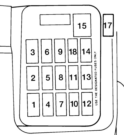
| Position | Rating [A] | Protected component / function |
|---|---|---|
| 1 | 10 A | A/C indicator, A/C relay and switch, DRL module and relay, rear wiper and washer, WOT relay. |
| 2 | 30 A | Power door-lock motors. |
| 3 | 20 A | Stop lamps, automatic-transmission control, PCM, center high-mounted stop lamp, horn, shift lock and speed control. |
| 4 | 15 A | Hazard lamps, front and rear turn signals and turn-signal indicator. |
| 5 | 30 A | Automatic seat-belt module and motor. |
| 6 | 15 A | PCM on 1.8 engine, exterior and interior lighting, parking-lamp relay and warning chime module. |
| 7 | 15 A | Dome/map lamp, power locks, ignition-switch and luggage-compartment lighting, Premium Sound, radio memory, PCM, shift lock and warning chime. |
| 8 | 30 A | Power windows. |
| 9 | 15 A | Power moonroof. |
| 10 | 15 A | Cooling fan and PCM power relay. |
| 11 | 15 A | Airbag module, reversing lamps, instrument cluster, flasher, automatic belts, Canadian PCM circuit, shift lock, speed control and warning chime. |
| 12 | 15 A | Illumination dimmer, radio and power mirrors. |
| 13 | 20 A | Front wipers and washer, intermittent-wiper control. |
| 14 | 20 A | PCM on 1.8 engine and heated rear window. |
| 15 | 30 A CB | Blower motor; on 1.8 models also PCM circuit – circuit breaker. |
| 16 | 20 A / 10 A | 1.8 BP: horn. 1.9 CVH: heated oxygen sensor (HEGO) and horn – connector side. |
| 17 | 20 A | Cigarette lighter / power outlet – connector side. |
| 18 | 10 A | 1.8 BP: ABS. |
Engine-compartment fuse box
The position numbering is shared, but several ratings depend on the 1.8 BP or 1.9 CVH engine and, in one case, the transmission type.
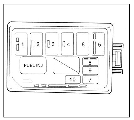
| Position | 1.8 BP | 1.9 CVH | Protected component / function |
|---|---|---|---|
| 1 | 30 A | 30 A | 1.8 charging system / fuel-injection system. |
| 2 | 30 A | 30 A | Canadian DRL, fog lamps, headlamps and high-beam indicator. |
| 3 | 80 A | 100 A | Main electrical-system feed, fuse panels, engine controls and starting system. |
| 4 | 60 A | 40 A | Passenger-compartment fuse-panel feed; on 1.9 also charging system. |
| 5 | 30 A MTX / 40 A ATX | 40 A | Cooling fan. |
| 6 | 20 A | 10 A | A/C compressor clutch; on 1.9 also PCM. |
| 7 | 10 A | 20 A | 1.8: fuel-pump relay and PCM. 1.9: fuel pump. |
| 8 | 60 A | – | ABS – 1.8 engine. |
| 9 | 10 A | 10 A | Airbag diagnostic monitor. |
| 10 | 20 A | 10 A | 1.8: fuel pump. 1.9: OBD-II / diagnostic connector. |
Commonly checked circuits
| Device | Position | Rating [A] | Location |
|---|---|---|---|
| Cigarette lighter / power outlet | 17 | 20 A | Passenger compartment |
| Front wipers | 13 | 20 A | Passenger compartment |
| Power windows | 8 | 30 A | Passenger compartment |
| Radio / mirrors | 12 | 15 A | Passenger compartment |
| Fuel pump – 1.8 | 10 | 20 A | Engine compartment |
| Fuel pump – 1.9 | 7 | 20 A | Engine compartment |
| ABS – 1.8 | 8 | 60 A | Engine compartment |
| Cooling fan | 5 | 30-40 A | Engine compartment |
Related model
The next generation uses a different electrical layout. See Mercury Tracer 1997-1999.
FAQ – Mercury Tracer 1991-1996 fuses
Where is the cigarette-lighter fuse?
Passenger-compartment position 17 – 20 A.
Where is the fuel-pump fuse?
On the 1.8 BP engine, check engine-compartment position 10 – 20 A. On the 1.9 CVH, check position 7 – 20 A.
Why does position 5 have two ratings on 1.8 models?
The 1.8 BP uses 30 A with the manual transmission and 40 A with the automatic transmission for the cooling-fan circuit.