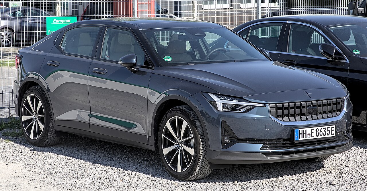
The Polestar 2 (introduced in 2020) uses two main low-voltage fuse boxes: one beneath the passenger glovebox and another in the front compartment. The following 2023 manufacturer’s fuse diagrams cover 68 cabin positions and 55 positions in the front fuse box. Each table preserves the original fuse number, amperage and Micro or MCase type.
Fuse positions are not continuous in every part of the passenger compartment: after 34, positions such as 40, 50, 60 and 80 occur. The factory numbering has been retained. Fuse fitment depends on drivetrain, model year and optional equipment, and later facelifts may not use exactly the same layout.
Where are the Polestar 2 fuse boxes?
Cabin: the fuse box is beneath the glovebox on the passenger side, behind a lower footwell trim panel. Once the trim is released according to the owner’s manual, the panel cover identifies the fuse locations. There is no need to dismantle the entire centre console to find this assembly.
Front compartment: the second unit is beneath the bonnet near the front luggage area (frunk), behind protective panels. Some access steps may require loosening panels around the storage compartment; avoid removing components not designated for owner access, and consult Polestar service if required.
Electric vehicle safety: the regular fuses here are not instructions for handling the high-voltage traction system. Never open high-voltage housings or touch orange cables. Polestar also specifies workshop servicing for certain slotted MCase and high-current fuse types.
Polestar 2 2023 passenger compartment fuse panel
This panel contains protection for the windows and locks, instrument and central displays, TCAM module, radar, sensors, front blower, seat equipment, steering-wheel heating and safety systems. Both fuse type and amperage matter when replacing a protection element.
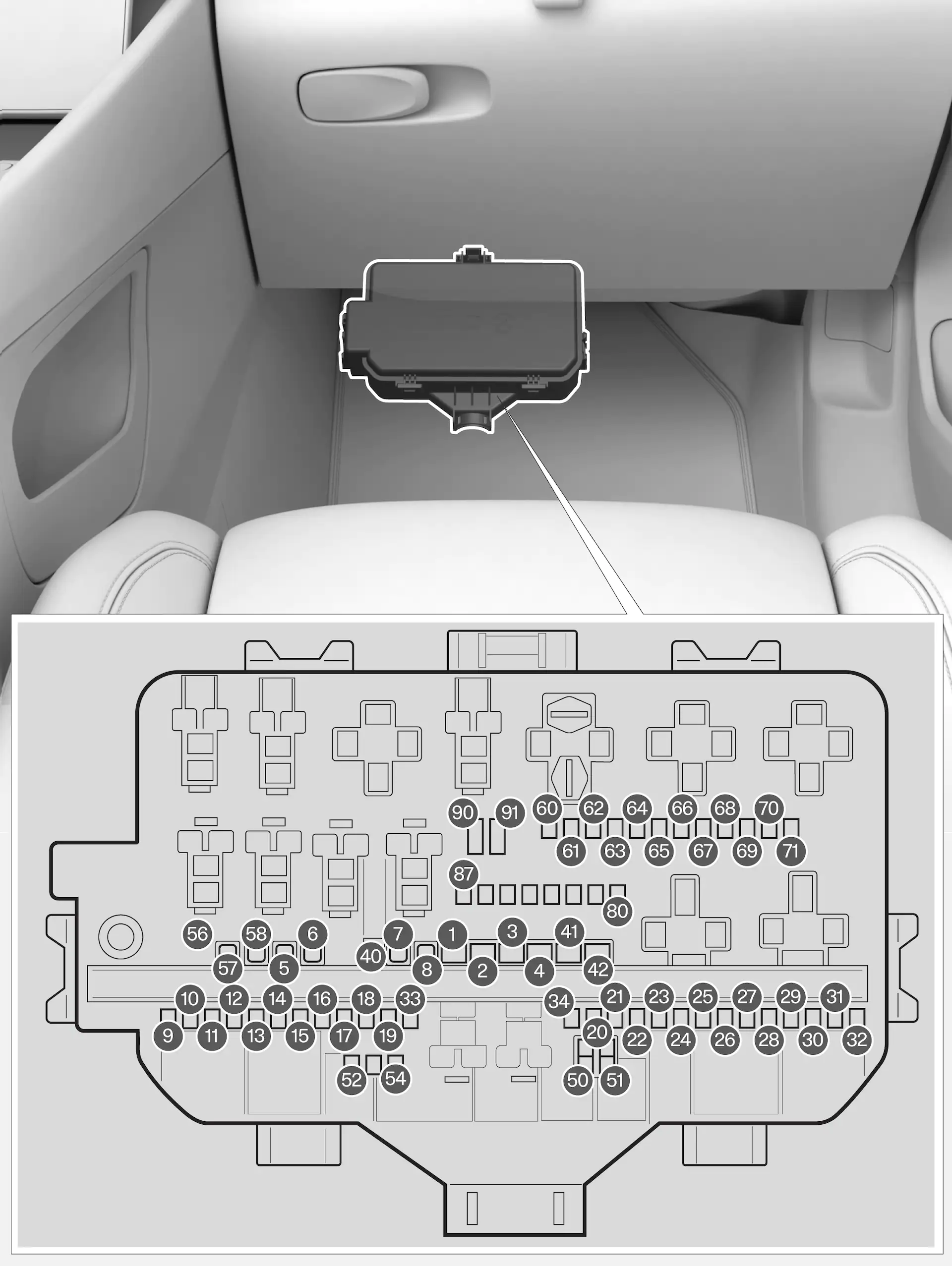
| Position | Amperage [A] | Protected circuit / function | Fuse type |
|---|---|---|---|
| 1 | 40 | Audio system amplifier | slotted MCase |
| 2 | 30 | Central Electronic Module A – sensors, radar and seats | slotted MCase |
| 3 | 30 | Central Electronic Module B – sensors, radar and seats | slotted MCase |
| 4 | 40 | Front HVAC blower motor | slotted MCase |
| 5 | 25 | Power tailgate | MCase |
| 6 | 20 | Left electric seat adjustment | MCase |
| 7 | 20 | Right electric seat adjustment | MCase |
| 8 | – | Unused / not assigned in the documented configuration | MCase |
| 9 | 20 | Right rear door module | Micro |
| 10 | 20 | Left rear door module | Micro |
| 11 | 20 | Left front door module | Micro |
| 12 | 15 | Rear vehicle lighting | Micro |
| 13 | 20 | Right front door module | Micro |
| 14 | 15 | Rear seat heating, if fitted | Micro |
| 15 | 5 | Rear electric motor inverter and ASDM safety module | Micro |
| 16 | 5 | Vehicle computing module | Micro |
| 17 | 5 | Sunlight sensor and electronic toll transponder | Micro |
| 18 | 7.5 | Steering column lock | Micro |
| 19 | 7.5 | Climate control module | Micro |
| 20 | 5 | Interior movement sensors, if fitted | Micro |
| 21 | 5 | Digital driver instrument cluster | Micro |
| 22 | 5 | Centre console switch panel | Micro |
| 23 | 5 | Steering wheel button module | Micro |
| 24 | 5 | Electronic gear selector module | Micro |
| 25 | 5 | Central infotainment touchscreen | Micro |
| 26 | 5 | Vehicle communications and connected services modules | Micro |
| 27 | 5 | TCAM antenna/communications module | Micro |
| 28 | 5 | Relay coil supply | Micro |
| 29 | 5 | Hands-free tailgate opening and Digital Key module, if fitted | Micro |
| 30 | 15 | Infotainment controller | Micro |
| 31 | 10 | OBD-II diagnostic connector | Micro |
| 32 | 5 | Alcohol interlock preparation, if fitted | Micro |
| 33 | – | Unused / not assigned | Micro |
| 34 | – | Unused / not assigned | Micro |
| 40 | 30 | Heated rear window | MCase |
| 41 | 40 | Left seatbelt pretensioner | MCase |
| 42 | 40 | Right seatbelt pretensioner | MCase |
| 50 | – | Unused / not assigned | Micro |
| 51 | – | Unused / not assigned | Micro |
| 52 | 7.5 | Coolant pump | Micro |
| 53 | 15 | Heated steering wheel, if fitted | Micro |
| 54 | 5 | Auxiliary electric heater | Micro |
| 55 | 25 | Headlamp washers | MCase |
| 56 | 25 | Front and rear window washers | MCase |
| 57 | – | Unused / not assigned | MCase |
| 58 | – | Unused / not assigned | MCase |
| 60 | – | Unused / not assigned | Micro |
| 61 | – | Unused / not assigned | Micro |
| 62 | – | Unused / not assigned | Micro |
| 63 | – | Unused / not assigned | Micro |
| 64 | 5 | BLIS blind spot monitoring, if fitted | Micro |
| 65 | – | Unused / not assigned | Micro |
| 66 | – | Unused / not assigned | Micro |
| 67 | 5 | Front radar control module | Micro |
| 68 | – | Unused / not assigned | Micro |
| 69 | – | Unused / not assigned | Micro |
| 70 | 5 | Provision for special vehicle version | Micro |
| 71 | 5 | Supplemental Restraint System (SRS) safety module | Micro |
| 80 | – | Unused / not assigned | Micro |
| 81 | 5 | 360-degree cameras, gear selector wake-up and overhead SRS indicator, depending on equipment | Micro |
| 82 | – | Unused / not assigned | Micro |
| 83 | 7.5 | Interior lighting, auto-dimming mirror, rain sensor, door panels and toll transponder | Micro |
| 84 | 5 | Wireless phone charger | Micro |
| 85 | 5 | Front camera | Micro |
| 86 | 5 | Alcohol interlock, if fitted | Micro |
| 87 | 5 | USB port | Micro |
| 90 | – | Unused / not assigned | Micro |
| 91 | – | Unused / not assigned | Micro |
Infotainment, communications and diagnostics
The main touchscreen uses cabin fuse 25 (5 A), while the infotainment control module uses 30 (15 A). TCAM is fuse 27 (5 A), the OBD-II diagnostic socket uses 31 (10 A) and the optional wireless phone charger uses 84 (5 A).
The windshield and rear-window washer system uses cabin fuse 56 (25 A), while headlight washers use 55 (25 A). Where fitted, the heated steering wheel uses 53 (15 A). BLIS blind-spot monitoring uses position 64 (5 A), and the front radar controller uses position 67 (5 A).
Polestar 2 2023 front compartment fuse panel
Under-bonnet circuits include electric motor cooling, traction battery thermal management, the onboard charger (OBC), headlamps, horn, front wipers and braking system. The diagram is a position guide: for any differences, follow the label on your actual vehicle and the correct owner’s manual.
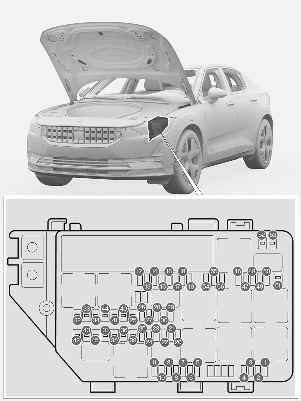
| Position | Amperage [A] | Protected circuit / function | Fuse type |
|---|---|---|---|
| 1 | 7.5 | Rear USB socket in centre console, optional | Micro |
| 2 | – | Unused / not assigned | Micro |
| 3 | – | Unused / not assigned | Micro |
| 4 | 15 | 12 V luggage compartment socket, optional | Micro |
| 5 | 10 | Electric motor control module | Micro |
| 6 | 15 | Electric motor cooling circuit | Micro |
| 7 | 5 | Traction battery cooling valve | Micro |
| 8 | 10 | Spoiler shutter and radiator grille shutter controllers | Micro |
| 9 | – | Unused / not assigned | Micro |
| 10 | – | Unused / not assigned | Micro |
| 11 | – | Unused / not assigned | Micro |
| 12 | 20 | Right headlamp | Micro |
| 13 | 20 | Left headlamp | Micro |
| 14 | 5 | Supplemental Restraint System (SRS) safety module | Micro |
| 15 | 5 | Accelerator pedal sensor | Micro |
| 16 | 5 | Power supply for drive, gearbox, steering, electronic and brake controllers when vehicle system is active | Micro |
| 17 | 5 | External acoustic warning module | Micro |
| 18 | 5 | Alcohol interlock preparation, optional | Micro |
| 19 | 10 | Rear vehicle lighting | Micro |
| 20 | 5 | Internal relay coils | Micro |
| 21 | – | Unused / not assigned | Micro |
| 22 | 5 | Brake pedal sensor | Micro |
| 23 | 5 | Vehicle computing unit | Micro |
| 24 | 5 | High-voltage battery control module | Micro |
| 25 | – | Unused / not assigned | Micro |
| 26 | 5 | Electric motor control module | Micro |
| 27 | 5 | On-board charger (OBC) | Micro |
| 28 | 5 | Front electric motor inverter | Micro |
| 29 | 20 | Horn | Micro |
| 30 | 5 | Security alarm siren, optional | Micro |
| 31 | 30 | Front windscreen wiper motor | MCase |
| 32 | – | Unused / not assigned | MCase |
| 33 | – | Unused / not assigned | MCase |
| 34 | – | Unused / not assigned | MCase |
| 35 | 30 | Brake system control module | MCase |
| 36 | – | Unused / not assigned | MCase |
| 38 | 30 | Headlamp electrical circuits | MCase |
| 39 | – | Unused / not assigned | MCase |
| 40 | – | Unused / not assigned | MCase |
| 41 | 25 | Towbar electrical system control, optional | MCase |
| 42 | 40 | Towbar electrical system control, optional | MCase |
| 43 | – | Unused / not assigned | MCase |
| 44 | – | Unused / not assigned | MCase |
| 45 | – | Unused / not assigned | MCase |
| 46 | 5 | External heat exchanger, optional | Micro |
| 47 | 5 | Air-conditioning compressor, high-voltage heater, expansion valve and monitoring unit | Micro |
| 48 | 15 | Traction battery controller and drive inverters | Micro |
| 49 | 20 | High-voltage traction battery coolant pump | Micro |
| 50 | 20 | Electric drive cooling pump | Micro |
| 51 | – | Unused / not assigned | MCase |
| 52 | – | Unused / not assigned | MCase |
| 53 | – | Unused / not assigned | MCase |
| 54 | – | Unused / not assigned | Micro |
| 55 | 20 | Left headlamp | Micro |
| 56 | 20 | Right headlamp | Micro |
Where are the USB and 12 V accessory fuses?
The optional rear USB socket in the centre console uses front-compartment position 1 (7.5 A). The optional luggage-compartment 12 V outlet uses front position 4 (15 A). A separate USB port is associated with cabin position 87 (5 A). Positions 2 and 3 of the front unit are unoccupied in this 2023 source layout.
Charging, electric drive and cooling fuses
Electric motor cooling uses front-compartment fuse 6 (15 A), and the traction battery coolant circuit valve uses 7 (5 A). The OBC charging system is listed at 27 (5 A). Traction battery and drive cooling pumps use positions 49 and 50 (20 A each). These are low-voltage power or control circuits, not high-voltage cable fuses.
The front wipers use position 31 (30 A, MCase); the horn uses 29 (20 A). The headlamp circuits appear at positions 12 and 13 (20 A each), with additional headlamp positions 55 and 56 in this variant.
Fuse types, equipment and 2024-onward revisions
The 2023 specification includes Micro, MCase and slotted MCase fuses. Never substitute one type or a different amperage solely because it fits a similarly sized slot. Optional systems such as a heated steering wheel, 360-degree cameras, towbar and power tailgate may be absent from individual cars.
For a closely related electric car, see our Volvo C40 Recharge 2023 fuse diagrams. For electric vehicles using a different architecture, see our Hyundai Ioniq 5, Kia EV6 and Skoda Enyaq fuse diagrams. Their fuse positions and ratings are not interchangeable with Polestar 2.
Polestar 2 fuse box FAQ
Where is the interior fuse box?
Below the passenger glovebox behind a lower footwell panel. The box lid shows the factory fuse positions.
Which fuse protects the optional 12 V luggage compartment outlet?
On the documented 2023 arrangement, front-compartment position 4 is rated at 15 A.
Which fuse powers the central touchscreen?
Cabin fuse 25 (5 A) supplies the central display, while fuse 30 (15 A) supplies the infotainment controller.
Does the 2023 layout work for a facelifted Polestar 2?
Not necessarily. Model-year updates, new electric drive components and fitted options can change the fuse allocations. Refer to the exact vehicle’s owner’s manual.
Fuse ratings and assignments: Polestar 2 official 2023 owner’s manual. Vehicle photograph: Alexander Migl, Wikimedia Commons, CC BY-SA 4.0.