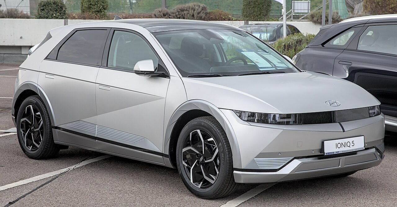
The Hyundai Ioniq 5 NE (launched in 2021) is an electric crossover with conventional 12 V fuses in the driver’s dashboard panel and in the front power compartment. The 2022 Hyundai fuse documentation lists 48 cabin positions, 15 high-current main fuses, 19 additional under-hood fuses, 15 PCB circuits and 10 relays.
Individual entries depend on model year, market, RWD or AWD powertrain and equipment such as the head-up display, solar roof and electric rear seats. Verify the manufacturer’s fuse box labels for the exact car before attempting replacement.
Where are the fuse boxes in a Hyundai Ioniq 5?
Passenger compartment: behind a removable lower dashboard cover on the driver’s side. Turn the vehicle off and wait for the READY indicator to go out. Remove the access panel gently and consult its fuse identification label.
Front power compartment: beside the auxiliary 12 V battery, inside the covered low-voltage fuse and relay distribution box. It houses regular fuses, high-current multi-fuse links, relays and the PCB block. Secure the cover carefully after inspection.
EV safety: do not disconnect orange high-voltage cables or open traction power enclosures. High-current links and other non-user-serviceable components should be handled by a technician trained to work with electric vehicles.
Hyundai Ioniq 5 2022 passenger compartment fuse panel
The cabin unit protects the doors, windows, eCall, powertrain control modules, air conditioning, seats, displays, USB outlets, central locking, safety systems and ADAS cameras and radar. The original fuse identification labels are retained in the first table column.
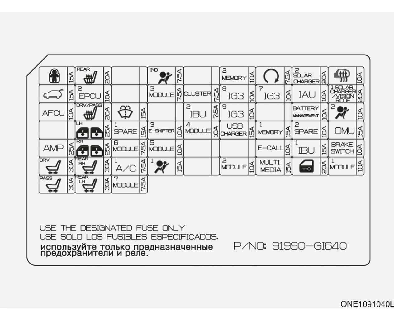
| Position | Amperage [A] | Protected circuit / function |
|---|---|---|
| Child Lock | 15 | Rear-door electric child safety lock relays |
| RR SEAT HTR | 20 | Rear heated seat control module |
| A/BAG IND | 7.5 | Overhead console airbag warning lamps and illumination |
| MEMORY2 | 10 | Head-up display (HUD), memory settings and cabin lighting |
| START | 7.5 | Vehicle Control Unit (VCU) and Integrated Body Control Unit (IBU) |
| S/CHARGE2 | 20 | Solar roof charging module supply |
| MIRR HTR | 10 | Heated door mirrors |
| T/GATE | 15 | Electric tailgate drive and controller |
| EPCU2 | 10 | Rear traction inverter control |
| MODULE3 | 7.5 | Multifunction switches, door electronics and brake lights |
| CLUSTER | 7.5 | Instrument cluster and head-up display (HUD) |
| IG3 8 | 10 | Vehicle-to-load (V2L), ICCU charging circuits and electric oil pump |
| IG3 7 | 10 | Multimedia, air conditioning and charging status indicator |
| IAU | 10 | Keyless entry and door-handle sensors |
| S/CHARGER/VISION ROOF | 20 | Solar roof panel and vision roof equipment |
| AFCU | 10 | AFCU module and keyless-entry components |
| FR SEAT HET | 20 | Front heated and ventilated seats |
| WASHER | 15 | Windscreen washer pump control |
| IBU2 | 7.5 | Integrated Body Control Unit (IBU) |
| IG3 9 | 10 | Rear traction inverter and high-voltage battery management |
| BMS | 10 | Traction battery management unit (BMU) |
| A/BAG2 | 10 | Airbag and seatbelt pretensioner controller |
| WIN LH | 25 | Left-side power windows |
| SPARE1 | 15 | Spare or unoccupied position |
| E-SHIFTER3 | 10 | Electronic drive selector |
| MODULE4 | 10 | Radar, front camera and driver assistance functions |
| USB CHARGER | 15 | Front USB charging outlets |
| MEMORY1 | 15 | Cabin lights, displays and memory functions |
| SPARE2 | 10 | Spare or unoccupied position |
| OMU | 15 | Electric exterior mirror operating modules |
| AMP | 25 | Audio amplifier |
| WIN RH | 25 | Right-side power windows |
| MODULE6 | 7.5 | Integrated Body Control Unit (IBU) power supply |
| MODULE5 | 10 | Diagnostic connector, eCall, mirror and multimedia equipment |
| E-CALL | 10 | Automatic emergency calling (eCall) |
| IBU1 | 15 | Integrated Body Control Unit (IBU) |
| BRAKE SWITCH | 10 | Brake lamp switch and brake pedal signal |
| P/SEAT DRV | 30 | Driver power seat motors and controller |
| P/SEAT RR RH | 30 | Right-hand rear electrically adjustable seat |
| A/C1 | 7.5 | Air-conditioning control electronics |
| A/BAG1 | 15 | Supplemental Restraint System (SRS) controller |
| MODULE2 | 10 | Audio amplifier, park assist and 12 V outlet module |
| MULTIMEDIA | 15 | Radio, screen and navigation |
| DR LOCK | 20 | Central door locking |
| MODULE1 | 10 | Lighting switches, rain sensor and seat controls |
| P/SEAT PASS | 30 | Power passenger seat motors and controller |
| P/SEAT RR LH | 30 | Left-hand rear electrically adjustable seat |
| MODULE7 | 7.5 | Rear seat heating control |
USB CHARGER (15 A) supplies front USB charging, MULTIMEDIA (15 A) covers infotainment, WASHER (15 A) covers the washers and MIRR HTR (10 A) supplies heated exterior mirrors.
Hyundai Ioniq 5 2022 front compartment – high-current fuses
The main low-voltage power distribution unit protects braking electronics, steering, climate controls, cabin fuse supply and the cooling fan. Some high-current elements are combined into a MULTI FUSE assembly and should not be removed like standard blade fuses.
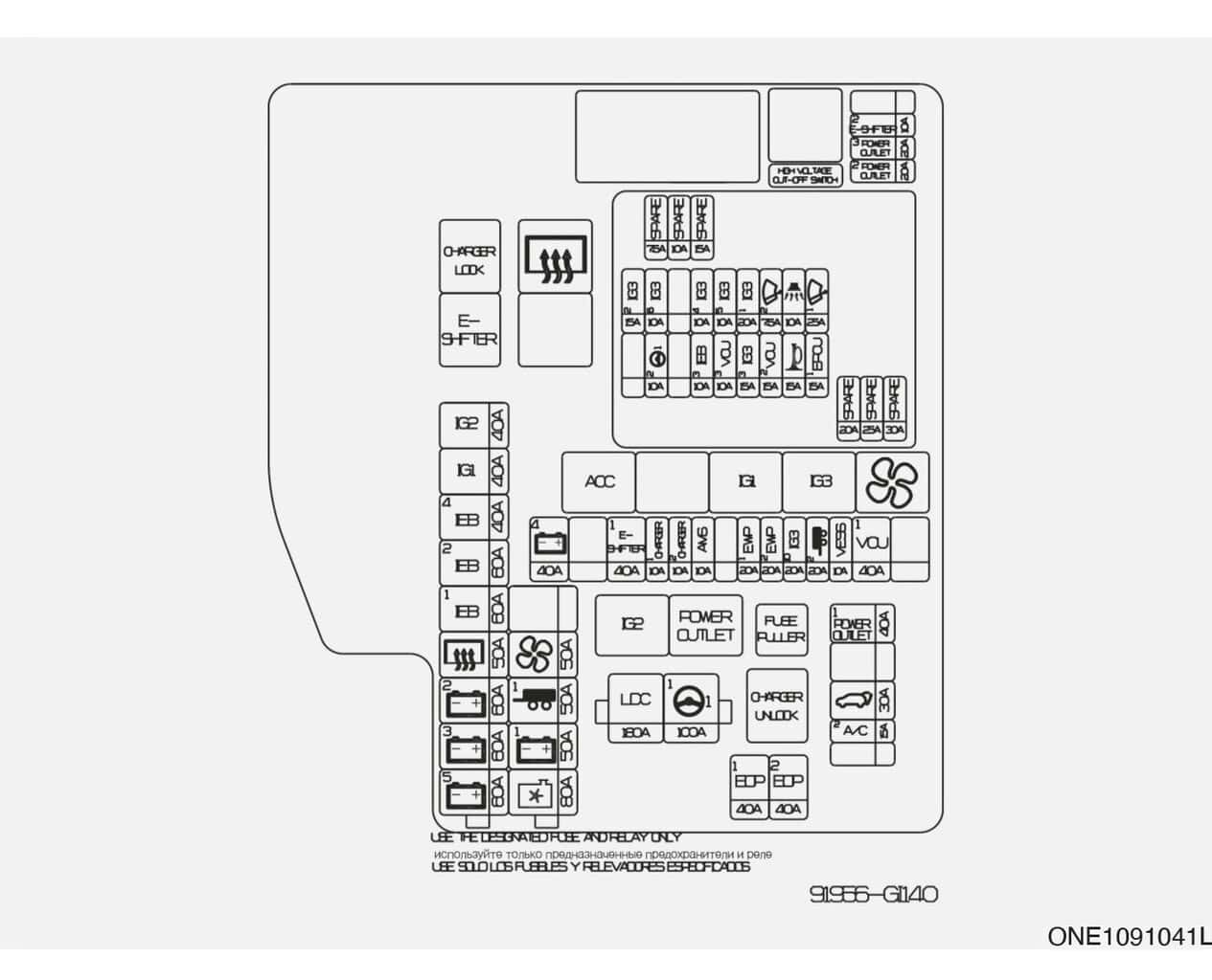
| Position | Amperage [A] | Protected circuit / function |
|---|---|---|
| LDC | 180 | Low-voltage DC/DC converter (LDC) and main distribution |
| MDPS1 | 100 | Main motor-driven power steering supply |
| B+5 | 60 | PCB block, IG3 relays and primary electrical protection |
| B+3 | 60 | Main passenger compartment fuse box feed |
| B+2 | 60 | Passenger compartment electronic modules |
| RR HTD | 50 | Rear window defogger and relay |
| IEB1 | 60 | Integrated Electronic Brake (IEB), circuit 1 |
| IEB2 | 60 | Integrated Electronic Brake (IEB), circuit 2 |
| IEB4 | 40 | Multi-purpose diagnostic connector electrical circuit |
| IG1 | 40 | IG1 and accessory relay power supply |
| IG2 | 40 | IG2 relay power supply |
| C/FAN | 80 | Engine-bay cooling fan |
| B+1 | 50 | Additional cabin distribution feed |
| TRAILER1 | 50 | Trailer electrical control module |
| BLOWER | 50 | Main cabin blower supply |
Additional front-compartment fuses
These 19 entries cover charging connector management, auxiliary battery sensing, electric cooling pumps, exterior power supply, tailgate, trailer wiring and additional drive components. They share the front fuse-box assembly but have separate labels from the multi-fuse positions.
| Position | Amperage [A] | Protected circuit / function |
|---|---|---|
| B+4 | 40 | Cabin modules and retained-power relay supply |
| E-SHIFTER1 | 40 | Electronic drive selector main supply |
| CHARGER1 | 10 | Charging connector lock relays and ICCU |
| CHARGER2 | 10 | Charging connector and Charging Control Module (CDM) |
| AMS | 10 | 12 V auxiliary battery sensor |
| EWP1 | 20 | Electric coolant pump 1 |
| EWP2 | 20 | Electric coolant pump 2 |
| IG3 10 | 20 | Additional IG3 electrical circuits |
| TRAILER2 | 20 | Trailer connector circuit 2 |
| VESS | 10 | Virtual Engine Sound System (VESS) pedestrian warning sound |
| VCU1 | 40 | Main Vehicle Control Unit (VCU) supply |
| P/OUTLET1 | 40 | Main 12 V outlet relay supply |
| T/GATE | 30 | Power tailgate motor and control |
| A/C2 | 15 | Air conditioning circuit |
| EOP1 | 40 | Rear electric drive-unit oil pump |
| EOP2 | 40 | Front electric drive-unit oil pump, AWD versions |
| E-SHIFTER2 | 10 | Electronic drive selector relay and controller |
| P/OUTLET3 | 20 | Rear 12 V power outlet |
| P/OUTLET2 | 20 | Front 12 V power outlet |
12 V sockets: front P/OUTLET2 (20 A), rear P/OUTLET3 (20 A) and outlet relay feed P/OUTLET1 (40 A). EWP1 and EWP2 are rated at 20 A each for coolant circulation.
Hyundai Ioniq 5 2022 PCB fuse block
The PCB block houses supplies for windshield wipers, horn, security alarm, EV cooling pumps, VCU, integrated brakes and the optional front inverter on AWD vehicles. Its ratings and positions are distinct from the high-current multi-fuse assembly.
| Position | Amperage [A] | Protected circuit / function |
|---|---|---|
| WIPER1 | 25 | Main windscreen wiper relay supply |
| EPCU1 | 15 | Front traction inverter, AWD versions |
| B/ALARM | 10 | Anti-theft alarm siren relay |
| HORN | 15 | Horn relay |
| WIPER2 | 7.5 | Wiper control through body electronics |
| VCU2 | 15 | Vehicle Control Unit (VCU) electronics |
| IG3 1 | 20 | Additional cabin IG3 supply circuits |
| IG3 3 | 15 | Electric coolant pump circuit |
| IG3 5 | 10 | Traction battery cooling three-way valve |
| VCU3 | 10 | Additional VCU circuit |
| IG3 4 | 10 | Cooling pumps and A/C compressor |
| IEB3 | 10 | Integrated Electronic Brake system (IEB) |
| IG3 6 | 10 | Cooling fan and front oil pump, AWD versions |
| MDPS2 | 10 | Motor-driven power steering controls |
| IG3 2 | 15 | Front inverter control, AWD versions, and VCU |
Front compartment relays (2022)
These relay designations cover IG and accessory power supplies, the charging connector lock and release, the electronic shift selector, HVAC blower, power outlets and rear window defogger. The relay table displays a dash instead of an amperage because relays are not blade fuses.
| Position | Relay type | Protected circuit / function |
|---|---|---|
| R1 | – | IG2 supply relay |
| R2 | – | 12 V power outlet relay |
| R3 | – | Charging connector unlock relay |
| R4 | – | Accessory supply (ACC) relay |
| R6 | – | IG1 supply relay |
| R7 | – | IG3 supply relay |
| R8 | – | Cabin blower relay |
| R9 | – | Charging connector lock relay |
| R10 | – | Electronic drive selector relay |
| R11 | – | Rear window defogger relay |
Model-year, equipment and RWD/AWD differences
The AWD drivetrain has extra front inverter and oil pump circuits not necessarily present on RWD models. Solar roof panels, power-adjustable rear seats and other options also affect the fuse layout. Later updates can change these assignments; follow the actual vehicle documentation.
The Kia EV6 CV uses a related E-GMP platform but is not identical in fuse assignments. For a smaller combustion-engine Hyundai, see the Hyundai Bayon fuse guide; its circuits should not be substituted for Ioniq 5.
What if a 12 V socket, USB port or washer fails?
For USB charging, check cabin USB CHARGER (15 A). The washer circuit uses cabin WASHER (15 A). For a 12 V outlet, check P/OUTLET2 (20 A) at the front or P/OUTLET3 (20 A) for the rear socket in the main front-compartment assembly. Unplug the faulty accessory before inspection.
The front wipers use PCB WIPER1 (25 A) and WIPER2 (7.5 A). Cabin blower power is supplied by BLOWER (50 A). Never install a fuse rated above the original specification; if it repeatedly fails, investigate the electrical load and circuit before replacement.
Hyundai Ioniq 5 fuse box FAQ
Where is the cabin fuse box?
Behind the lower dashboard panel on the driver’s side. Its inside label shows the fuses fitted to the car.
Which fuse supplies the front 12 V outlet?
In the 2022 configuration, P/OUTLET2 is rated at 20 A and located in the front fuse assembly.
Does the 2022 fuse diagram match a 2025 Ioniq 5?
Not necessarily. Year, market, battery/drivetrain configuration and equipment changes can affect fuse locations and ratings. Use the correct model-specific cover label and documentation.
Should I replace high-voltage traction fuses myself?
No. Never dismantle high-voltage protection or orange wiring. These components require electric vehicle service training and appropriate safety procedures.
Fuse information: Hyundai Ioniq 5 NE 2022 official Polish owner’s manual and relay documentation. Vehicle photograph: Alexander Migl, Wikimedia Commons, CC BY-SA 4.0.