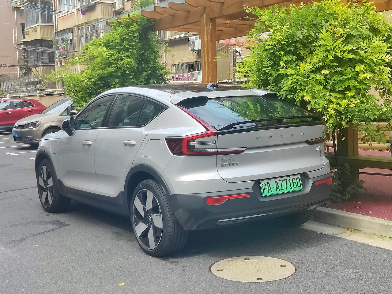
The Volvo C40 Recharge (2021-2024) is an electric crossover with low-voltage fuse boxes under the passenger glovebox and in the front compartment. The following tables reproduce Volvo’s 2023 documentation (22w46): 67 interior and 56 under-bonnet fuse positions, including unused slots, ratings and fuse types.
Do not confuse the battery-electric C40 Recharge with the plug-in hybrid XC40 Recharge or assume that every later EC40 retains the same layout. Individual circuits vary by model year, drivetrain, market and options. Before replacing a fuse, check the label and manufacturer’s manual for the actual car.
Where are the Volvo C40 Recharge fuse boxes?
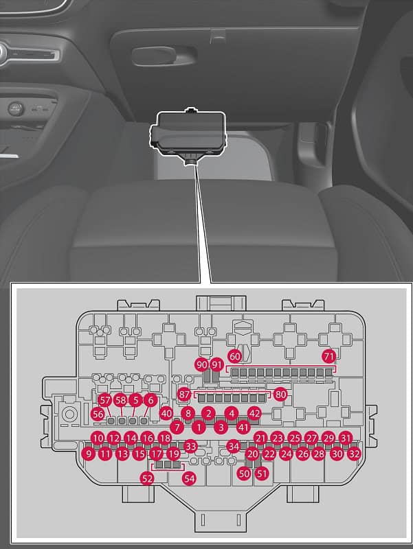
Cabin: behind the fuse-box cover below the passenger glovebox. Move the passenger footwell mat and release the panel catches as described by Volvo. On a left-hand-drive car this fuse box is on the passenger side, not beside the steering column.
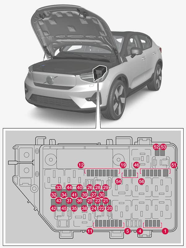
Front compartment: under protective panels around the front luggage compartment (frunk). Follow Volvo’s instructions for accessing the user-serviceable lid, and do not remove protected high-voltage covers or touch orange wiring.
Volvo C40 Recharge 2023 – cabin fuses
These 67 entries cover door modules, displays, audio, climate control, seat electronics, diagnostic equipment and optional systems. Fuse numbering is not continuous after position 34; the original manufacturer numbers have been retained.
| Position | Amperage [A] | Protected circuit | Fuse type |
|---|---|---|---|
| 1 | 40 | Audio amplifier | Slotted MCase |
| 2 | 40 | Central electronic module (CEM) A | Slotted MCase |
| 3 | 40 | Central electronic module (CEM) B | Slotted MCase |
| 4 | 40 | Front HVAC blower | Slotted MCase |
| 5 | 25 | Power tailgate | MCase |
| 6 | 20 | Left power seat | MCase |
| 7 | 20 | Right power seat | MCase |
| 8 | – | Unused position | MCase |
| 9 | 20 | Right rear door controller | Micro |
| 10 | 20 | Left rear door controller | Micro |
| 11 | 20 | Left front door controller | Micro |
| 12 | 15 | Rear exterior lighting | Micro |
| 13 | 20 | Right door controller | Micro |
| 14 | – | Unused position | Micro |
| 15 | 5 | ASDM safety module and rear motor inverter | Micro |
| 16 | 5 | Vehicle computing module | Micro |
| 17 | 5 | Sunlight sensor and toll transponder | Micro |
| 18 | 7.5 | Steering column lock | Micro |
| 19 | 7.5 | Climate control | Micro |
| 20 | 5 | Interior motion sensors | Micro |
| 21 | 5 | Driver display | Micro |
| 22 | 5 | Centre console buttons | Micro |
| 23 | 5 | Steering wheel switches | Micro |
| 24 | 5 | Electronic gear selector | Micro |
| 25 | 5 | Central touchscreen | Micro |
| 26 | 5 | Connected vehicle services | Micro |
| 27 | 5 | TCAM antenna | Micro |
| 28 | 5 | Relay coils | Micro |
| 29 | 5 | Hands-free tailgate opening | Micro |
| 30 | 15 | Infotainment system | Micro |
| 31 | 10 | OBD-II diagnostic socket | Micro |
| 32 | – | Unused position | Micro |
| 33 | 15 | Left rear head restraint | Micro |
| 34 | 15 | Right rear head restraint | Micro |
| 40 | 30 | Rear window defogger | MCase+ |
| 41 | 40 | Left seatbelt pretensioner | MCase+ HT |
| 42 | 40 | Right seatbelt pretensioner | MCase+ HT |
| 50 | – | Unused position | Micro |
| 51 | – | Unused position | Micro |
| 52 | 7.5 | Coolant pump | Micro |
| 53 | 15 | Heated steering wheel | Micro |
| 54 | 5 | Humidity and air particle sensors | Micro |
| 55 | 25 | Headlight washers | MCase+ |
| 56 | 25 | Windscreen washers | MCase+ |
| 57 | – | Unused position | MCase |
| 58 | – | Unused position | MCase |
| 60 | – | Unused position | Micro |
| 61 | – | Unused position | Micro |
| 62 | – | Unused position | Micro |
| 63 | – | Unused position | Micro |
| 64 | 5 | Blind Spot Information System (BLIS) | Micro |
| 65 | – | Unused position | Micro |
| 66 | – | Unused position | Micro |
| 67 | 5 | Front radar | Micro |
| 68 | – | Unused position | Micro |
| 69 | – | Unused position | Micro |
| 70 | – | Unused position | Micro |
| 71 | 5 | Airbags and seatbelt pretensioner controller | Micro |
| 80 | – | Unused position | Micro |
| 81 | 5 | Electronic gear selection, roof console indicator and panoramic/360-degree cameras | Micro |
| 83 | 7.5 | Interior lights, rear-view mirror, rain/light sensors and rear door/tailgate controls | Micro |
| 84 | 5 | Wireless phone charger | Micro |
| 85 | 5 | Front camera | Micro |
| 86 | – | Unused position | Micro |
| 87 | 5 | USB sockets | Micro |
| 90 | – | Unused position | Micro |
| 91 | – | Unused position | Micro |
Common circuits: central display position 25 (5 A), infotainment position 30 (15 A), TCAM antenna 27 (5 A), OBD-II connector 31 (10 A), wireless phone charging 84 (5 A) and USB outlets 87 (5 A). Windscreen washers use 56 (25 A), headlamp washers 55 (25 A), heated steering wheel 53 (15 A), BLIS 64 (5 A) and front radar 67 (5 A) where equipped.
Volvo C40 Recharge 2023 – front compartment fuses
The front electrical distribution box protects electric-drive control modules, brake circuits, battery cooling, the onboard charger, headlamps, horn, wipers and power outlets. Micro, MCase, MCase+ and specialised slotted fuses appear in the documentation; type and amperage both matter.
| Position | Amperage [A] | Protected circuit | Fuse type |
|---|---|---|---|
| 1 | 7.5 | Rear USB ports in centre console | Micro |
| 2 | 15 | Front 12 V power outlet in centre console | Micro |
| 3 | – | Unused position | Micro |
| 4 | – | Unused position | Micro |
| 5 | 10 | Electric Motor Control Module (ECM) | Micro |
| 6 | 15 | Traction battery coolant shut-off valve | Micro |
| 7 | 5 | Traction battery coolant pump | Micro |
| 8 | 10 | Spoiler shutter and radiator controls | Micro |
| 9 | – | Unused position | Micro |
| 10 | – | Unused position | Micro |
| 11 | – | Unused position | Micro |
| 12 | 20 | Right headlamp | Micro |
| 13 | 20 | Left headlamp | Micro |
| 14 | 5 | SRS safety module and passenger presence sensor (COS) | Micro |
| 15 | 5 | Accelerator pedal | Micro |
| 16 | 5 | Ignition-switched feed for motor, transmission, steering, electronics and brakes | Micro |
| 17 | 5 | Diagnostic gateway and external vehicle warning sound | Micro |
| 18 | – | Unused position | Micro |
| 19 | 10 | Rear exterior lights | Micro |
| 20 | 5 | Relay coils | Micro |
| 21 | – | Unused position | Micro |
| 22 | 5 | Brake pedal sensor | Micro |
| 23 | 5 | Vehicle computing module | Micro |
| 24 | 5 | Traction battery controls | Micro |
| 25 | – | Unused position | Micro |
| 26 | 5 | Electric Motor Control Module (ECM) | Micro |
| 27 | 5 | Onboard charging module | Micro |
| 28 | 5 | Front motor inverter | Micro |
| 29 | 20 | Horn | Micro |
| 30 | 5 | Alarm siren | Micro |
| 31 | 30 | Windscreen wipers | MCase |
| 32 | – | Unused position | Slotted MCase |
| 33 | – | Unused position | Slotted MCase |
| 34 | – | Unused position | Slotted MCase |
| 35 | 30 | Brake control circuits | MCase |
| 36 | – | Unused position | MCase |
| 37 | – | Unused position | MCase |
| 38 | 30 | Headlamp circuits | MCase |
| 39 | – | Unused position | MCase |
| 40 | – | Unused position | MCase |
| 41 | 25 | Towbar electrics | MCase |
| 42 | 40 | Towbar electrics | MCase |
| 43 | – | Unused position | Slotted MCase |
| 44 | – | Unused position | Slotted MCase |
| 45 | – | Unused position | Slotted MCase |
| 46 | 5 | External heat exchanger | Micro |
| 47 | 5 | High-voltage converter, A/C compressor, switching valve and monitoring controls | Micro |
| 48 | 15 | Traction battery, front and rear motor inverters | Micro |
| 49 | 20 | Traction battery coolant pump | Micro |
| 50 | 20 | Traction battery coolant pump | Micro |
| 51 | – | Unused position | Micro |
| 52 | – | Unused position | Slotted MCase |
| 53 | – | Unused position | Slotted MCase |
| 54 | – | Unused position | Micro |
| 55 | 20 | Left headlamp | Micro |
| 56 | 20 | Right headlamp | Micro |
Where are the 12 V, USB and infotainment fuses?
For the 2023 version, the front 12 V accessory outlet in the centre console uses front-compartment fuse 2 (15 A). Rear centre-console USB ports use front fuse 1 (7.5 A), while other cabin USB connections use interior fuse 87 (5 A). These sockets do not necessarily share the same supply circuit.
The main central display uses interior fuse 25 (5 A). Infotainment electronics are supplied by interior fuse 30 (15 A). Never install a stronger fuse to compensate for a repeated overload.
Traction battery cooling, charging, lights and wipers
The traction battery control supply appears at front position 24 (5 A), with the charging module at 27 (5 A). Coolant pumps are protected at positions 49 and 50 (20 A each), and the battery coolant shut-off valve uses 6 (15 A). These are auxiliary supply/control circuits and do not make the high-voltage traction system safe to service.
Front wipers use fuse 31 (30 A, MCase) and horn fuse 29 (20 A). Headlamps are assigned to positions 12 and 13 (20 A each), plus 38 (30 A), 55 and 56 (20 A each) for additional circuits. Optional trailer wiring uses positions 41 (25 A) and 42 (40 A).
Fuse types, model years and the EC40 name
Depending on market and production date, electric motor arrangements, cooling hardware and safety equipment can differ. The source lists Micro, MCase, MCase+, MCase+ HT and slotted MCase fuses. Do not substitute one form for another merely because its current rating matches, and leave restricted high-current protection to a qualified workshop.
For a related vehicle see the Polestar 2 fuse diagrams. For independent electric-vehicle comparisons, consult the Hyundai Ioniq 5 and Kia EV6. Do not interchange fuse positions between models.
Volvo C40 Recharge fuse box FAQ
Where is the cabin fuse box?
Under the glovebox on the passenger side. Follow the Volvo instructions for moving the floor mat and releasing its cover.
Which fuse supplies the front 12 V outlet?
Front-compartment fuse 2, rated 15 A in the documented 2023 configuration.
Which fuse supplies the central touchscreen?
Interior fuse 25 is 5 A. The infotainment controller is a separate circuit at interior fuse 30, 15 A.
Are Volvo C40 Recharge and later EC40 fuse assignments necessarily identical?
No. Drivetrain and equipment changes can alter the positions and ratings. Verify the car’s own manual and fuse labels.
Fuse information: Volvo Cars C40 Recharge 2023 owner’s manual, version 22w46. Vehicle photograph: Evnerd, Wikimedia Commons, CC BY-SA 4.0.