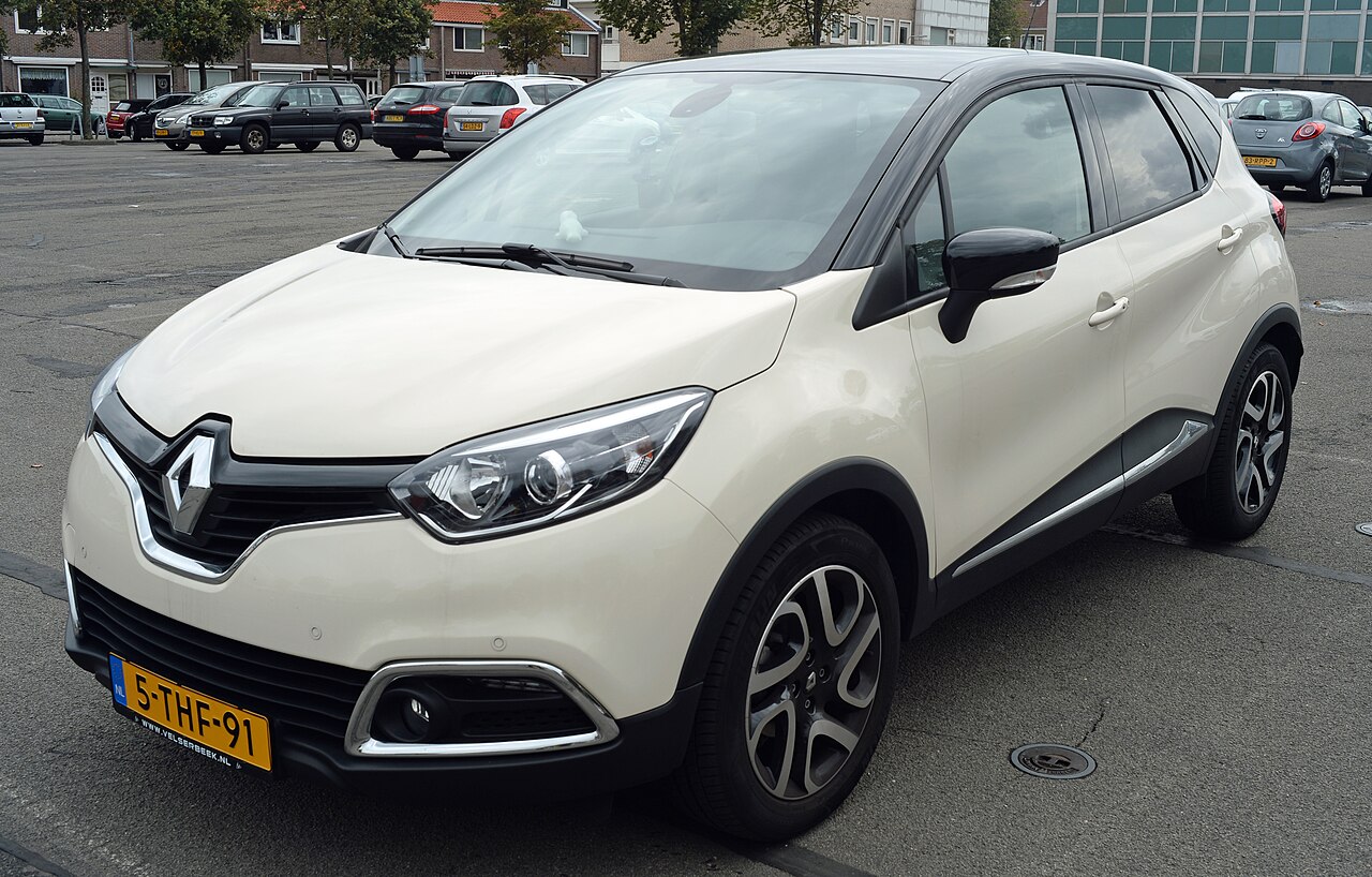
The first-generation Renault Captur I (J87, 2014-2016) has a passenger-compartment fuse panel and further electrical protection under the bonnet. The main owner’s guide identifies 39 interior fuse positions, while some 2016 electrical variants add a separate F-numbered fuse set and R-numbered relays.
Different engines, including H5F403 petrol and K9K diesel, can use different front-compartment fuse and relay modules. The general cabin list does not contain universal amperage ratings, so a dash indicates an unconfirmed rating, not an unused fuse. Look at the original fuse and exact vehicle diagram before replacing it.
Renault Captur I fuse box locations
Cabin: behind the removable cover in the lower dashboard on the driver’s side. Turn the ignition off first, and use the fuse puller where provided. The position number should be matched to your own cover chart.
Engine compartment: further modules protect the starter, coolant fan, ABS and injection system. The front panels vary with petrol and diesel powertrains; do not use cabin F numbers for an under-bonnet unit or transfer a fuse rating from another engine.
Renault Captur 2014-2016 cabin fuse box 1-39
This is the 39-position owner’s list for the first-generation Captur. It describes headlights, wipers, interior electronics, central locking and accessories without assigning fabricated current ratings. Some positions are unused or optional in particular builds.

| Position | Rating [A] / type | Protected circuit / function |
|---|---|---|
| 1 | – | Manufacturer’s combined circuit list: power steering, heated front seats and radio |
| 2 | – | Fuel injection and daytime running lights |
| 3 | – | Airbags and safety system control |
| 4 | – | Automatic transmission |
| 5 | – | Dipped-beam headlights |
| 6 | – | Front fog lamps, position lights and main beams |
| 7 | – | Horn |
| 8 | – | Left high-beam headlamp |
| 9 | – | Right high-beam headlamp |
| 10 | – | Right dipped beam and right daytime running lamp |
| 11 | – | Left dipped-beam headlamp |
| 12 | – | Left position lights, front sidelights and left daytime running lamp |
| 13 | – | Right position lights, front fog lamps and rear sidelights |
| 14 | – | Rear windscreen wiper |
| 15 | – | Electric power steering |
| 16 | – | Headlamp height adjustment and injection control |
| 17 | – | Daytime running lights and brake lights |
| 18 | – | Headlamp adjustment and brake lights |
| 19 | – | Electric door mirror controls |
| 20 | – | ABS and ESP electronic stability system |
| 21 | – | Interior lighting |
| 22 | – | Engine start and stop button |
| 23 | – | Radio |
| 24 | – | UCH passenger-compartment body controller |
| 25 | – | UCH passenger-compartment body controller, second circuit |
| 26 | – | Direction indicators |
| 27 | – | Central locking of doors and other opening panels |
| 28 | – | Power management module |
| 29 | – | Power management module, second circuit |
| 30 | – | Alarm system |
| 31 | – | Instrument cluster |
| 32 | – | Cigarette lighter and 12 V socket |
| 33 | – | Rear fog lamp |
| 34 | – | Front seat heating |
| 35 | – | Heated rear windscreen |
| 36 | – | Towbar circuit, if fitted |
| 37 | – | Front windscreen wipers |
| 38 | – | Unused in this documented layout |
| 39 | – | Front windscreen wipers, second circuit |
Captur additional interior fuses F1-F8
Selected 2016 models use another electrical distribution section with F1, F2, F3 and F5-F8 listed below. These entries are separate from the main 1-39 cabin layout; even similarly numbered positions must not be conflated.
| Position | Rating [A] / type | Protected circuit / function |
|---|---|---|
| F1 | 30 | Rear power windows |
| F2 | 30 | Front power windows |
| F3 | 30 | Heater and air-conditioning blower |
| F5 | 25 | Driver power window |
| F6 | 15 | Radio and UCH body controller |
| F7 | 10 | Front fog lamps |
| F8 | 20 | Heated rear window circuit |
Renault Captur interior relays R1-R6
In certain configurations six relay positions govern ignition-switched supplies, accessories, child locks, electric windows and the heated rear window. These are relays, not blade fuses, and may not all be populated.
| Position | Rating [A] / type | Protected circuit / function |
|---|---|---|
| R1 | Relay | Ignition-switched supply, circuit 2 |
| R2 | Relay | Accessory electrical power supply |
| R3 | Relay | Child safety locking |
| R4 | Relay | Electric windows |
| R5 | Relay | Heated rear window |
| R6 | Relay | Power window control |
Under-bonnet fuses depend on Captur engine version
On an H5F403 petrol-engine layout, for example, starter protection may use Fb1 (30 A), while another protected ABS/ESP circuit is identified as F3 (30 A) and electric steering as F8 (80 A). These are examples from one engine-bay specification, not universal assignments for all 0.9 TCe, 1.2 TCe or 1.5 dCi vehicles. The source does not provide a complete matching engine-bay table for all powertrains.
Captur I cigarette lighter, radio, horn and wiper fuses
Cigarette lighter or front 12 V socket: main cabin position 32. A documented 2016 variant uses 15 A, but check the original installed fuse on your car. Radio: main cabin position 23; some versions also use auxiliary F6 (15 A).
Central locking: main position 27. Rear wiper: position 14. Front wipers: positions 37 and 39. Heated rear window: position 35; optional electrical layouts may also include auxiliary F8 and relay R5.
Headlamps: high beams are associated with positions 8 and 9, with dipped-beam and daytime running functions involving 5, 10 and 11. Do not substitute another model’s headlamp fuse values.
Renault Captur I, Clio IV and Captur II
The Captur I has related components to the Renault Clio IV, but that does not make its assignments identical. The Renault Captur II is a newer generation with substantially different fuse numbering and electrical equipment.
Renault Captur I fuse box FAQ
Where is the passenger compartment fuse box?
Behind the lower driver’s-side dashboard cover.
Which fuse is used for the cigarette lighter?
Main cabin position 32; check the actual ampere rating on the vehicle.
Which fuses are used for the front wipers?
The main cabin list identifies positions 37 and 39; the rear wiper uses 14.
Are the additional F1-F8 positions part of the main 1-39 list?
No. They belong to a separate optional electrical distribution configuration.
Never increase a fuse rating to stop repeat failures. Inspect the protected equipment and wiring instead.