
The Hyundai i10 III AC3 (2020) is the European third-generation i10 city car. It has a driver’s-side passenger-compartment fuse box and an engine-bay fuse, relay and main-power distribution carrier beside the battery. These diagrams are for the AC3 electrical installation, not the earlier second-generation i10 or the Grand i10 Nios sold in other regions.
This English guide retains all 79 active and spare entries in the Polish manufacturer’s manual listing: 41 cabin rows and 38 engine-bay relay or fuse positions. The engine source table also has five group separator rows, which are presented here as an explanatory group legend rather than as imaginary fuse positions. Manual and AMT gearbox, ISG Stop & Start and optional equipment differences are noted.
Hyundai i10 AC3 fuse box locations and access
Driver-side dashboard: park safely, switch off the ignition and all electrical equipment, then open the driver’s door. Release the lower fuse cover to the left of the steering column. The lid carries the vehicle-specific fuse symbols and ratings. Use the plastic fuse puller kept in the engine-bay box to remove a small fuse straight out and replace it only with the same amperage.
Engine compartment: lift the bonnet and find the covered fuse / relay box by the battery. Press its securing clip and raise the lid. Match the fuse name and rating on the inside of the cover; do not rely on the table row order to locate a physical slot.
Depending on options, additional high-current links may be installed in an adjacent power-distribution housing. The 80-150 A main fuses require manufacturer-approved battery isolation and workshop procedures. Close all fuse covers securely to prevent moisture damage.
Interior fuse panel – 41 entries from the 2020 manual
Positions 1-41 follow the order of the factory table, which may not be printed as slot numbers on the physical fuse lid. Find each fuse by its original name, location and rating on that lid. HEATED STEERING is a 15 A circuit at table entry 21 when equipped, as confirmed by Hyundai’s owner’s manual.
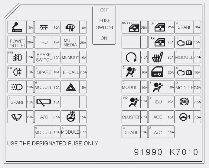
| Pozycja | Amperaż [A] | Chroniony obwód / funkcja |
|---|---|---|
| 1 | 15 | HAZARD – direction indicators and hazard warning lights |
| 2 | 20 | DOOR LOCK – central locking and unlocking |
| 3 | 15 | FRONT FOG LAMP – front fog lights if equipped |
| 4 | 10 | BRAKE SWITCH – brake pedal stop-lamp switch |
| 5 | 25 | POWER WINDOW LH – left-side electric window |
| 6 | 25 | POWER WINDOW RH – right-side electric window |
| 7 | 25 | POWER WINDOW SAFETY – driver’s anti-pinch window protection |
| 8 | 20 | POWER OUTLET – front 12 V accessory socket |
| 9 | 15 | CIGAR LIGHTER – 12 V cigarette lighter socket |
| 10 | 10 | ACC – low-voltage DC converter (LDC), eCall, audio, navigation and IBU |
| 11 | 10 | HEATED MIRROR – exterior mirror heating |
| 12 | 7.5 | AIR BAG IND – airbag warning lamp and instrument cluster |
| 13 | 10 | AIR BAG 1 – SRS control module (SRSCM) |
| 14 | 10 | AIR BAG 2 – second SRS controller feed |
| 15 | 10 | INTERIOR LAMP – cabin, glovebox and luggage lights |
| 16 | 20 | MULTI MEDIA – radio / navigation and LDC power converter |
| 17 | 7.5 | MDPS – electric power steering control |
| 18 | 20 | SEAT HEATER – heated front seats, if equipped |
| 19 | 7.5 | ABS – anti-lock braking system controller |
| 20 | 7.5 | CLUSTER – instrument cluster |
| 21 | 15 | HEATED STEERING – heated steering wheel where fitted |
| 22 | 7.5 | E-CALL – factory emergency call system |
| 23 | 15 | TCU – clutch sensor, transmission selector and reverse gear switch |
| 24 | 10 | ECU – engine control module (ECM) |
| 25 | 10 | REAR FOG LAMP – rear fog light |
| 26 | 10 | DRL – daytime running lamps |
| 27 | 15 | WIPER RR – rear wiper motor and multifunction stalk switch |
| 28 | 20 | WIPER FRT – front windscreen wiper system |
| 29 | 7.5 | START – starter motor relay |
| 30 | 7.5 | A/C 1 – climate control unit and blower relay |
| 31 | 7.5 | A/C 2 – air conditioning and blower motor controls |
| 32 | 7.5 | MODULE 1 – brake switch signal |
| 33 | 10 | MODULE 2 – Integrated Body Control Unit (IBU), parking sensors, ESC switch and centre console |
| 34 | 7.5 | MODULE 3 – OBD diagnostics, eCall, AMT gear display, lamps and audio |
| 35 | 7.5 | MODULE 4 – IBU and door locking control (SLM) |
| 36 | 10 | MODULE 5 – IBU and heated seat controls |
| 37 | 10 | MODULE 6 – central locking switch and OBD diagnostics |
| 38 | 10 | MEMORY – climate and instrument settings memory |
| 39 | 15 | IBU 1 – first body controller supply |
| 40 | 10 | IBU 2 – second body controller supply |
| 41 | 10 | SPARE – factory spare fuse, not an active circuit |
Engine fuse and relay box – all 38 devices
The factory listing contains separate groups of relay ratings and fuse circuits. To distinguish similarly named parts, the first column uses editorial codes: R1-R9 for relays, H for high-current links, J for cartridge fuses, M for larger circuit protection and L for mini fuses. These codes help identify the listed parts but are not manufacturer-assigned physical cavity numbers.
For relay rows R1-R9, the figure in the “Amperaż [A]” column is the relay contact rating, not a replacement blade fuse value. Engine-bay AMT 1, AMT 2 and AMT 3 apply only to vehicles with the automated manual transmission.
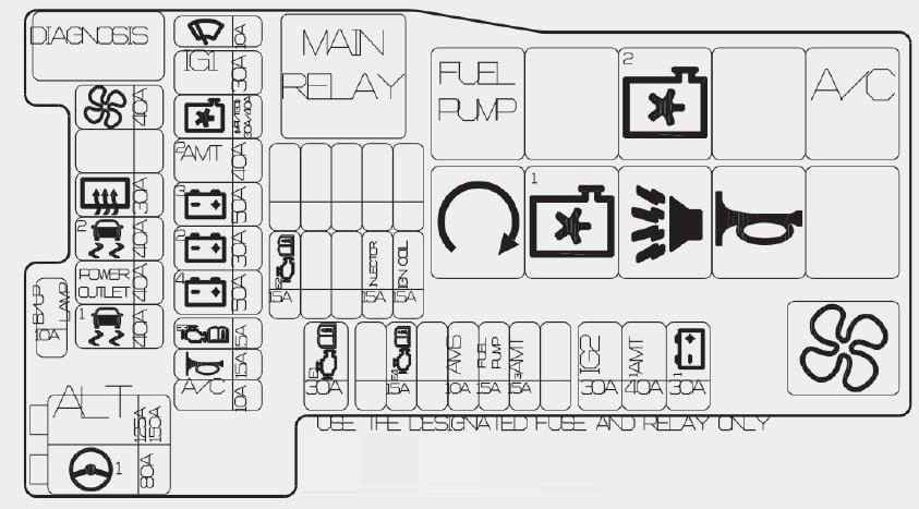
| Pozycja | Amperaż [A] | Chroniony obwód / funkcja |
|---|---|---|
| R1 | 30 | MAIN relay – engine ECU and manual / AMT power supply |
| R2 | 20 | FUEL PUMP relay – fuel pump |
| R3 | 35 | COOLING FAN 1 relay – radiator fan high speed |
| R4 | 35 | COOLING FAN 2 relay – radiator fan low speed |
| R5 | 20 | A/C relay – air conditioning compressor |
| R6 | 20 | START relay – engine controller supply during cranking |
| R7 | 20 | BUGLER ALARM HORN relay – factory alarm siren |
| R8 | 20 | HORN relay – audible horn |
| R9 | 35 | BLOWER relay – cabin ventilation blower |
| H-ALT | 125/150 | ALTERNATOR main high-current fuse – 125 or 150 A depending on equipment |
| H-MDPS | 80 | MDPS main power steering fuse |
| J-BLW | 40 | BLOWER main cabin ventilation fan feed through ICU |
| J-RHT | 30 | REAR HEATED – heated rear window supply |
| J-AM1 | 40 | AMT 1 – first actuator/control circuit for automated manual transmission |
| J-AM2 | 40 | AMT 2 – second actuator/control circuit for automated manual transmission |
| J-B1 | 30 | BATTERY 1 – ICU battery feed circuit one |
| J-B2 | 30 | BATTERY 2 – ICU battery feed circuit two |
| J-B3 | 50 | BATTERY 3 – ICU battery feed circuit three |
| J-B4 | 50 | BATTERY 4 – ICU battery feed circuit four |
| J-FAN | 30/40 | COOLING FAN main motor feed – 30 or 40 A depending on variant |
| M-ESC1 | 40 | ESC 1 – first stability control module supply |
| M-ESC2 | 40 | ESC 2 – second stability control module supply |
| M-OUT | 40 | POWER OUTLET – high-current feed to accessory socket relay |
| M-IG1 | 30 | IGNITION 1 – ignition-switched supply for ICU |
| M-IG2 | 30 | IGNITION 2 – second ignition and starter solenoid circuit |
| M-ECU1 | 30 | ECU 1 – main ECM power supply |
| L-REV | 10 | BACK UP LAMP – reversing light |
| L-WIP | 10 | WIPER – wiper and engine controller signal supply |
| L-FUEL | 15 | FUEL PUMP – fuse for fuel pump, separate from R2 relay |
| L-HORN | 15 | HORN – horn fuse, separate from R8 relay |
| L-A/C | 10 | AIR CONDITIONER – compressor control |
| L-ECU2 | 15 | ECU 2 – first main ECU relay supply |
| L-ECU3 | 15 | ECU 3 – second main ECU relay supply |
| L-ECU4 | 15 | ECU 4 – third main ECU relay supply |
| L-INJ | 15 | INJECTOR – fuel injectors |
| L-COIL | 15 | IGNITION COIL – ignition coils |
| L-AMT3 | 15 | AMT 3 – third AMT control circuit |
| L-AMS | 10 | AMS – battery condition monitoring sensor |
Engine, ISG and equipment variations
1.0 MPI and 1.2 MPI: they share many electrical circuit names, but engine sensors, connectors and ECU supplies depend on the actual engine. AMT: the automated manual gearbox uses its own actuator feeds; manual-gearbox cars may have these positions unpopulated.
ISG / Stop & Start: battery and charging management also depend on equipment. ALTERNATOR can be protected by a 125 or 150 A main link, while COOLING FAN uses a 30 or 40 A feed in the documented variants. Never substitute the higher-rated link without checking the vehicle’s fuse chart.
Optional comfort equipment: heated steering, heated seats and front fog lights may not be installed in lower trim levels. A spare fuse at cabin position 41 is provided as a replacement part and does not protect an operating circuit.
Common Hyundai i10 2020 electrical faults
Front 12 V socket not working: cabin position 8 POWER OUTLET (20 A). The lighter socket uses separate cabin position 9 CIGAR LIGHTER (15 A). Engine box M-OUT (40 A) is a main accessory supply, not a substitute for either small fuse.
Front wipers stopped: inspect cabin position 28 WIPER FRT (20 A), and the engine L-WIP control circuit (10 A). The rear wiper uses cabin position 27 (15 A); check the tailgate wiring as well if only the rear motor fails.
Central locking fault: cabin DOOR LOCK position 2 (20 A) is the first point to check. Heated steering not working: cabin position 21 HEATED STEERING (15 A), if the car has this option.
No heater blower: engine J-BLW (40 A) and blower relay R9 protect the main fan feed. Cabin A/C 1 and A/C 2 are separate 7.5 A controls. If the blower works only at full speed, test the fan regulator rather than replacing unrelated fuses.
Horn silent: engine L-HORN fuse (15 A) and relay R8 are separate. Engine will not start: investigate the battery, grounds, cabin START (7.5 A), engine IGNITION 2 and ECU 1 rather than assuming every fault is due to the starter relay.
ABS/ESC warning: cabin ABS (7.5 A) and engine M-ESC1 / M-ESC2 (40 A each) are part of the supply chain. If the correct fuses are intact, diagnostic fault codes are needed. Do not fit a larger fuse to conceal a short circuit.
For another European city car with a separate body fuse panel and engine fuse carrier, see Toyota Aygo X (2022). The Hyundai and Toyota fuse allocations are not interchangeable.