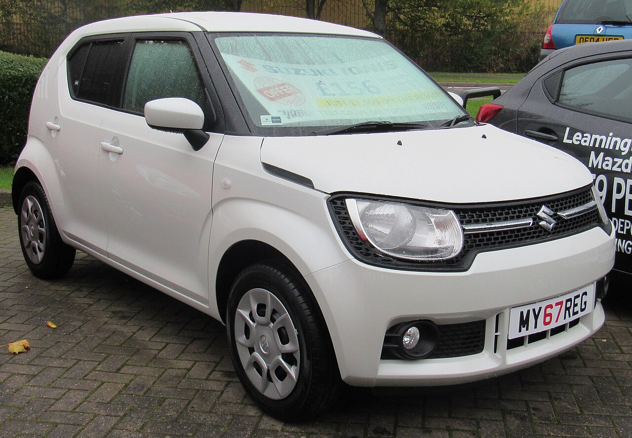
Suzuki Ignis III (MF, 2017-2018) with the 1.2 Dualjet K12C petrol engine uses two main fuse carriers: one in the engine bay next to the battery and another beneath the driver-side dashboard. The documented configuration contains 37 under-bonnet positions and 38 interior positions, including main links FL1-FL6, unused sockets and variants for ENG A-STOP, CVT and Auto Gear Shift (AGS).
The diagram and fuse list are based on the earlier K12C installation in Suzuki’s owner’s manual. The later K12D engine introduced in revised Ignis versions has a different engine-bay fuse assignment. Do not transfer its engine numbers into a 2017 K12C car.
Where are the Suzuki Ignis 2017-2018 fuse boxes?
Engine compartment: switch off the engine, ignition, lamps and blower. Open the bonnet and locate the plastic fuse carrier cover next to the battery. Press the retaining clips, remove the cover and read its original labels for the engine and ABS circuits. Main fusible links FL1-FL6 can be mounted in a separate high-current section; they require the manufacturer’s service procedure.
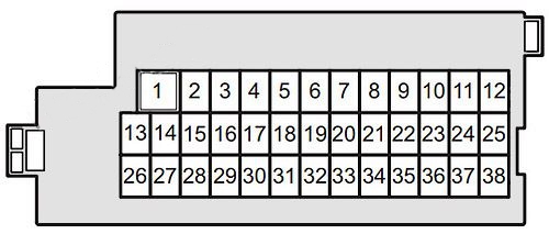
Passenger compartment: open the driver door and look beneath the lower dashboard near the steering column. The 38-position panel uses the layout illustrated below. Remove the correct blade fuse with the supplied plastic puller and replace it only with the same rating. On right-hand-drive vehicles, check the actual fuse panel access location.
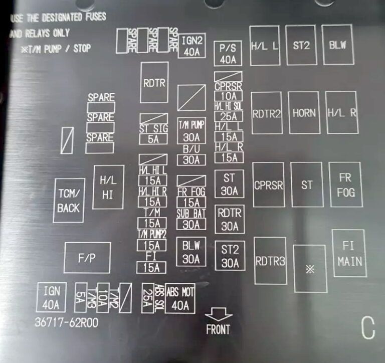
Engine compartment fuse box – positions 1-37
The photographed 2018 engine box cover identifies the circuit symbols but does not depict a fully numbered 37-position fuse carrier. The table uses Suzuki’s 2017 K12C manual numbering, including the separate FL1-FL6 main links. Confirm the exact position on the vehicle’s own fuse lid.
| Pozycja | Amperaż [A] | Chroniony obwód / funkcja |
|---|---|---|
| 1 | 120 | FL1 – main electrical supply, fusible link |
| 2 | 100 | FL2 – main distribution feed, fusible link |
| 3 | 80 | FL3 – power distribution for selected vehicle circuits |
| 4 | 100 | FL4 – main grouped power supply |
| 5 | 50 | FL5 – group fusible link |
| 6 | 150 | FL6 – main feed for vehicles with ENG A-STOP |
| 7 | 40 | Electric power steering |
| 8 | – | Unused position |
| 9 | 10 | Air conditioning compressor |
| 10 | 25 | High-beam headlamp feed on versions with automatic headlights |
| 11 | 15 | Left headlamp |
| 12 | 15 | Right headlamp |
| 13 | 30 | Starter motor |
| 14 | 30 | Radiator cooling fan |
| 15 | 30 | Secondary starter supply on CVT models with ENG A-STOP |
| 16 | 40 | Ignition switch supply circuit 2 |
| 17 | – | Unused position |
| 18 | 30 | Auto Gear Shift (AGS) transmission pump |
| 19 | 30 | Back-up / constant supply circuit |
| 20 | – | Unused position |
| 21 | 15 | Front fog lights, if fitted |
| 22 | 30 | Auxiliary battery on ENG A-STOP cars |
| 23 | 30 | Cabin blower motor |
| 24 | – | Unused position |
| 25 | 5 | Starter signal |
| 26 | – | Unused position |
| 27 | 15 | Left high beam on automatic-headlight cars |
| 28 | 15 | Right high beam on automatic-headlight cars |
| 29 | 15 | CVT transmission with ENG A-STOP |
| 30 | 15 | Secondary CVT pump on ENG A-STOP-equipped models |
| 31 | 15 | Fuel injection (FI) |
| 32 | 40 | ABS hydraulic pump motor |
| 33 | 25 | ABS solenoid valves |
| 34 | – | Unused position |
| 35 | 10 | AGS transmission controller circuit 2 |
| 36 | 5 | AGS transmission controller circuit 3 |
| 37 | 40 | Main ignition switch power supply |
Driver-side fuse box – all 38 positions
The interior fuse carrier uses positions 1-38 in three rows. The same 38-position numbered layout is documented in Suzuki’s earlier Ignis manual. Position 32 ACC-2 (15 A) serves the 12 V accessory outlet; 34 (10 A) is for the rear wiper and 37 (25 A) for the front wipers. Positions 6 and 7 are unused.
| Pozycja | Amperaż [A] | Chroniony obwód / funkcja |
|---|---|---|
| 1 | 30 | Electric windows |
| 2 | 10 | Instrument cluster |
| 3 | 15 | Ignition coils |
| 4 | 5 | Ignition-1 signal circuit 2 |
| 5 | 20 | Gear shift lever |
| 6 | – | Unused position |
| 7 | – | Unused position |
| 8 | 20 | Central door locks |
| 9 | 15 | Steering lock |
| 10 | 10 | Hazard warning lights |
| 11 | 5 | ENG A-STOP controller |
| 12 | 10 | Rear fog light |
| 13 | 5 | ABS / ESP controller |
| 14 | 15 | Heated front seats, if fitted |
| 15 | 5 | Ignition-1 signal circuit 3 |
| 16 | 10 | Second interior lighting circuit |
| 17 | 5 | First interior lighting circuit |
| 18 | 15 | Radio / audio system |
| 19 | 5 | CONT circuit |
| 20 | 5 | Keyless system, secondary supply |
| 21 | 20 | Electric-window timer relay |
| 22 | 5 | Keyless system, primary supply |
| 23 | 15 | Horn |
| 24 | 5 | Left side / parking lamps |
| 25 | 10 | Side and tail lamps |
| 26 | 10 | Airbag controller (SRS) |
| 27 | 10 | Ignition-1 signal |
| 28 | 10 | Reversing lamps |
| 29 | 5 | ACC3 accessory equipment |
| 30 | 20 | Heated rear window / rear defogger |
| 31 | 10 | Heated exterior mirrors |
| 32 | 15 | 12 V accessory socket (ACC2) |
| 33 | 5 | Audio and accessory circuits |
| 34 | 10 | Rear windscreen wiper |
| 35 | 5 | Ignition-2 signal |
| 36 | 15 | Windscreen washer pump |
| 37 | 25 | Front windscreen wiper motor |
| 38 | 10 | Brake / stop lamps |
A-STOP, AGS, CVT and optional lighting
ENG A-STOP: cars with idle-stop have additional battery control and main FL6 protection. CVT plus A-STOP: some cars use engine positions 15, 29 and 30. Auto Gear Shift (AGS): the electronically controlled automated manual gearbox can require engine positions 18, 35 and 36.
Automatic headlights: positions 10, 27 and 28 are equipment-specific. Position 21 supplies front fog lights where installed. An unoccupied slot on a base model must not be filled just because the fuse appears in another Ignis variant.
Suzuki Ignis electrical troubleshooting
12 V socket dead: check cabin position 32, ACC2 (15 A), and inspect the outlet for metal objects or a faulty charging accessory. Front wipers stopped: cabin position 37 (25 A); rear wiper position 34 (10 A). Check the motor and linkage if the fuse is intact.
No cabin blower: under-bonnet position 23 (30 A) protects the blower feed. Heated rear window failure: cabin position 30 (20 A), then the relay and heater connections.
Headlamp failure: engine position 11 (15 A) is the left headlamp and 12 (15 A) the right. Horn failure: cabin position 23 (15 A), then horn wiring and switching.
Starting problem: check battery condition and the under-bonnet starter signal position 25 (5 A) and fuel injection circuit position 31 (15 A). Cars with ENG A-STOP, CVT or AGS may require diagnostic checks of the relevant transmission or starting controller.
ABS warning or steering assistance failure: inspect the appropriate ABS feeds at engine positions 32 and 33, and the steering supply at engine position 7 (40 A). If those fuses are correct, diagnose the affected control unit instead of raising a fuse rating or disconnecting the safety system.
Related English guides for compact cars include SEAT Mii (2013) and Toyota Aygo X (2022). Their fuse assignments are different from the Ignis.