
Škoda Felicia (6U, 1994-2001) was built as a hatchback, estate, pick-up and utility model. Common engine options included 1.3 and 1.6-litre petrol units and a 1.9-litre diesel. It uses an interior fuse-and-relay panel with 22 numbered fuses and 10 relay/module designations, including INT and W-W.
This English reference preserves every position and all three diagrams from the Polish article. Some circuits differ by production year, engine and equipment, particularly electric windows, ABS/EDS, air conditioning and optional accessories. The printed label on the actual fuse holder takes precedence over a general internet diagram.
Where is the Škoda Felicia fuse box?
The main fuse and relay panel is under the passenger-side dashboard. Release the retaining fastener and lower the panel gently. The small blade fuses are in its lower area, with relays in the upper row. The precise relay population can vary with engine and equipment.
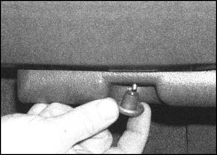
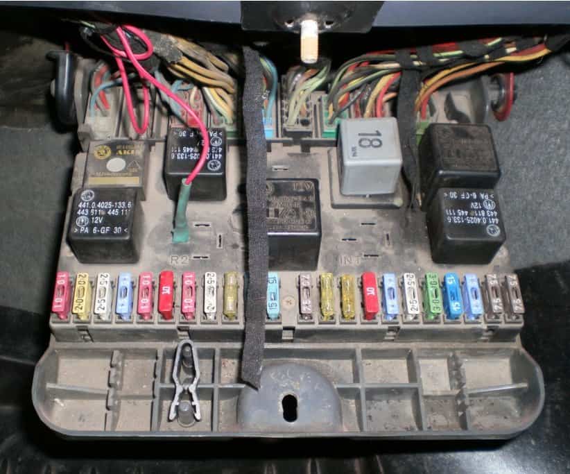
Škoda Felicia 1994-2001 fuse diagram: positions 1-22
The main panel protects engine control, headlights, indicators, heating, powered accessories, wipers and rear glass. Fuse 15 (15 A) supplies the cigarette lighter/12 V socket, the interior lighting and the clock. Fuse 2 (20 A) covers the front and rear windscreen wipers and washers; fuse 3 (25 A) the heater blower.
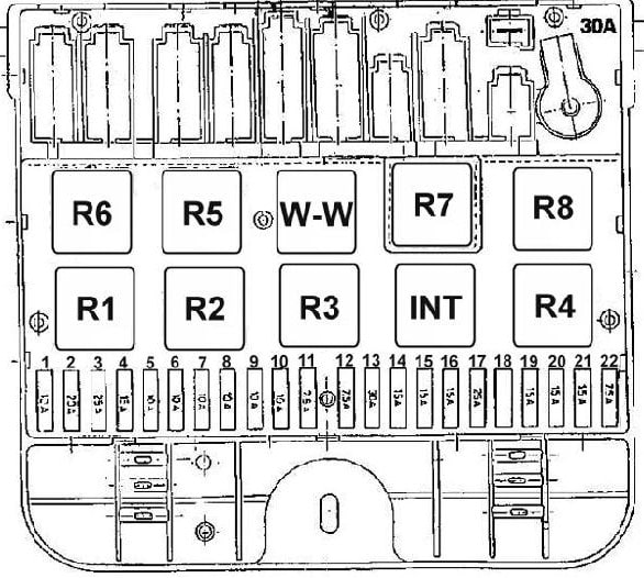
| Position | Rating | Protected circuit |
|---|---|---|
| 1 | 10 A | Fuel injection system controller power supply |
| 2 | 20 A | Front and rear windscreen wipers and washers |
| 3 | 25 A | Heater blower, air conditioning if equipped |
| 4 | 15 A | Engine management power, sometimes including injection, fuel pump and lambda sensor depending on engine |
| 5 | 10 A | Right front fog lamp |
| 6 | 10 A | Left front fog lamp and warning light |
| 7 | 10 A | Right dipped-beam headlamp |
| 8 | 10 A | Left dipped-beam headlamp and warning light |
| 9 | 10 A | Right high-beam headlamp |
| 10 | 10 A | Left high-beam headlamp and warning light |
| 11 | 7,5 A | Right front/rear position lamps and lights-left-on warning buzzer |
| 12 | 7,5 A | Rear fog lamp and warning light |
| 13 | 30 A | Heated rear window and indicator, optional heated mirrors |
| 14 | 15 A | Brake lamps, indicators and hazard lights; ABS/EDS circuits in selected versions |
| 15 | 15 A | Cigarette lighter/12 V outlet, cabin lighting and clock |
| 16 | 15 A | Headlamp washer pump or central locking module, if equipped |
| 17 | 25 A | Radiator fan, horn and headlamp-flash circuit |
| 18 | 25 A* | Electric windows on fitted cars; unused in versions without power windows |
| 19 | 15 A | Instrument cluster and warnings, charging circuit, rear heater, airbags, mirrors and heated seats depending on equipment |
| 20 | 15 A | Carburettor or fuel injection module, immobiliser and ignition system according to engine |
| 21 | 15 A | Direction indicators and reversing lamps |
| 22 | 7,5 A | Left position lamps, licence plate and boot lighting, dashboard/button illumination, radio and mirror controls depending on equipment |
Fuse 18 (25 A) serves electric windows where fitted but may be unpopulated on cars without them. Fuse 13 (30 A) controls rear-window heating, and fuse 17 (25 A) is associated with the radiator fan and horn. Optional ABS/EDS protection may have additional feeds outside the main cabin panel.
Felicia cigarette lighter, wipers, lamps and fuel pump diagnosis
For a dead lighter socket, remove connected devices and inspect fuse 15 (15 A), then the socket contacts. Fuse 2 (20 A) covers windscreen cleaning and wiper circuits; the separate INT and W-W relays help control rear and intermittent wiping.
For lighting faults, check the individual left/right beam positions: dipped beams 7 and 8 (10 A each), high beams 9 and 10 (10 A each). Fuel injection controller power is protected at fuse 1 (10 A) and, depending on the engine, additional power may be on fuse 4 (15 A) and fuse 20 (15 A). The Bosch Mono-Motronic fuel-pump relay is listed at R5; this does not mean every Felicia has the same injection system.
Škoda Felicia relay chart
The upper fuse unit includes conventional relays R1 to R8 and the additional INT and W-W wiper controls. Relays absent from a particular car may simply correspond to equipment that was not installed.
| Relay | Function |
|---|---|
| R1 | High-beam headlamp relay |
| R2 | Front fog lamp relay |
| R3 | Rear fog lamp relay |
| R4 | Heated rear window relay |
| R5 | Injection system/fuel pump relay on Bosch Mono-Motronic versions |
| R6 | Ignition and open-door warning/interlock device on selected vehicles only |
| R7 | Ignition switch load-reduction X-relay |
| R8 | Hazard warning light relay |
| INT | Rear windscreen wiper and washer relay |
| W-W | Front windscreen wiper intermittent-operation relay |
Additional fuse protection in the engine compartment
Some Felicia versions have supplementary fuses under the bonnet on the left-hand side. Depending on engine and equipment these may protect the ABS, air-conditioning compressor, radiator fan and, on the 1.9 D diesel, pre-heating. Because these positions and amperages are not listed consistently in the source, no universal extra fuse numbers are invented here.
For newer Škoda electrical layouts, see the Škoda Fabia I (1999-2007) or Škoda Citigo (2012). Their numbering is different and should not be copied to the Felicia.
Škoda Felicia 1994-2001 fuse box FAQ
Where is the main fuse box?
Below the passenger-side dashboard, in the drop-down fuse and relay holder.
Which fuse protects the cigarette lighter?
Fuse 15 (15 A); it also serves interior lighting and the clock.
Which fuse protects the front wipers?
Fuse 2 (20 A), which supplies windscreen wiper and washer equipment.
Does position 18 always contain a fuse?
No. Its 25 A power-window protection is installed only on equipped versions; other cars may leave it unused.
Are all relays identical across 1.3, 1.6 and 1.9 D engines?
No. The relay population depends on the engine electronics and installed equipment.
Replace any blown fuse only with the correct manufacturer’s type and rating. Repeated failure requires examining the wiring and connected equipment, not increasing the fuse amperage.