
Škoda Fabia I (6Y, 1999-2007) was sold as a hatchback, saloon and estate. Its electrical system includes 68 positions in the interior fuse panel and a separate high-current distribution block above the battery. Depending on engine, production year and equipment, the battery block has either 16 or 12 numbered positions. Do not mix these two layouts.
This guide reproduces all 96 rows in three complete tables from the Polish article, including the original diagrams and unoccupied sockets. The year 2007 overlaps the launch of Fabia II (5J), whose interior panel has only 58 positions; Fabia III (NJ) has 59. Always identify the generation before fitting a fuse.
Where are the Škoda Fabia I fuse boxes?
Passenger compartment: open the driver’s door and release the cover on the left end of the dashboard. The blade-fuse positions are numbered 1-68. Some right-hand-drive versions have mirrored access arrangements.
Engine compartment: a separate high-current block sits on top of the battery beneath a plastic cover. The alternator, electric steering, radiator fan, ABS/ESP and diesel glow plugs are protected here. Work on the very large main fuses should follow the manufacturer’s workshop instructions.
Fabia I interior fuse box: positions 1-68
Cigarette lighter and cabin 12 V socket: position 42 (15 A). Radio/navigation: 45 (20 A). Front wipers: 41 (20 A), and rear wiper: 32 (10 A). Fuel pump on petrol models: 61 (15 A); diesel injection electronics have different positions.
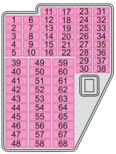
| Position | Rating [A] | Protected circuit / function |
|---|---|---|
| 1 | 5 | Instrument cluster and ESP stability system |
| 2 | 10 | Brake lights |
| 3 | 5 | Diagnostic connector power and climate control |
| 4 | 10 | Interior lighting |
| 5 | 5 | Door-open warning light |
| 6 | 5 | Headlamp beam levelling |
| 7 | 5 | Engine controls and power steering |
| 8 | – | Unused |
| 9 | 10 | Oxygen (lambda) sensor |
| 10 | 5 | Terminal S (ignition/key sensing), footnote a |
| 11 | 5 | Electric door mirror adjustment, footnote b |
| 12 | 5 | Air recirculation, air conditioning and Xenon headlights |
| 13 | 10 | Reversing light |
| 14 | 10 | Diesel engine control unit |
| 15 | 10 | Headlamp washers and wipers |
| 16 | 5 | Instrument cluster |
| 17 | 5 | Petrol engine control unit, footnote c |
| 18 | 5 | Telephone |
| 19 | 10 | Automatic transmission |
| 20 | 5 | Bulb failure monitoring control unit |
| 21 | 5 | Heated washer jets |
| 22 | – | Unused |
| 23 | 10 | Right high-beam headlamp |
| 24 | 10 | Engine management |
| 25 | 5 | ABS and ASR controllers |
| 26 | – | Unused |
| 27 | – | Unused |
| 28 | 5 | Cruise control and brake/clutch pedal switches |
| 29 | – | Unused |
| 30 | 10 | Left high-beam headlamp and telltale |
| 31 | 10 | Central locking, doors and boot lid |
| 32 | 10 | Rear window wiper |
| 33 | 5 | Right-side position lights |
| 34 | 5 | Left-side position lights |
| 35 | 10 | Petrol fuel injectors |
| 36 | 5 | Registration plate lighting |
| 37 | 5 | Rear fog lamp and warning indicator |
| 38 | 5 | Heated door mirrors |
| 39 | 20 | Heated rear window |
| 40 | 20 | Horn |
| 41 | 20 | Front windscreen wipers |
| 42 | 15 | Cigarette lighter and interior 12 V socket |
| 43 | 20 | Central control module and automatic gearbox selector lock |
| 44 | 15 | Direction indicators |
| 45 | 20 | Radio and navigation |
| 46 | 25 | Front right electric window |
| 47 | – | Unused |
| 48 | 30 | Diesel engine controller and fuel injection pump |
| 49 | 15 | Central door locking |
| 50 | 15 | Right dipped-beam headlamp |
| 51 | 15 | Luggage compartment 12 V socket |
| 52 | 15 | Ignition system |
| 53 | 25 | Rear right electric window |
| 54 | 15 | Left dipped-beam headlamp |
| 55 | – | Unused |
| 56 | 20 | Petrol engine controller |
| 57 | 25 | Towbar wiring |
| 58 | 25 | Front left electric window |
| 59 | – | Unused |
| 60 | 15 | Alarm siren |
| 61 | 15 | Petrol fuel pump |
| 62 | 25 | Electric tilt-and-slide sunroof |
| 63 | 15 | Seat heating |
| 64 | 20 | Headlamp washing system |
| 65 | 15 | Front fog lamps |
| 66 | 25 | Rear left electric window |
| 67 | – | Unused |
| 68 | 25 | Heater blower motor |
For other frequent faults check horn fuse 40 (20 A), heated rear window fuse 39 (20 A), air conditioner/diagnostic power fuse 3 (5 A), and cargo-area 12 V socket fuse 51 (15 A). An unused location must remain unpopulated unless the vehicle’s equipment and wiring specify otherwise.
Battery-top high-current fuse box: 16 positions
In this arrangement position 1 (175 A) protects alternator/battery charging and position 2 (110 A) feeds the interior. Position 3 (50 A) supplies electric power steering, 4 (40 A) diesel glow plugs where fitted, and 5 and 8 (40 A / 30 A) cooling fan circuits. ABS/ASR/ESP uses positions 6 and 7.
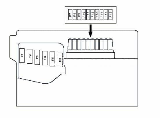
| Position | Rating [A] | Protected circuit / function |
|---|---|---|
| 1 | 175 | Battery charging and alternator |
| 2 | 110 | Main passenger compartment electrical supply |
| 3 | 50 | Electric power steering |
| 4 | 40 | Diesel glow plug heating |
| 5 | 40 | Radiator cooling fan |
| 6 | 40 | ABS, ASR or ESP control system |
| 7 | 25 | ABS, ASR or ESP power supply |
| 8 | 30 | Radiator fan secondary circuit |
| 9 | – | Unused |
| 10 | 5 | Central control module |
| 11 | 5 | Air conditioning system |
| 12 | – | Unused |
| 13 | 5 | Automatic transmission controller |
| 14 | – | Unused |
| 15 | – | Unused |
| 16 | – | Unused |
Alternative battery-top fuse box: 12 positions
The second variant is not a shortened continuation of the first. Here position 3 (40 A) protects the radiator fan, 4 (40 A) ABS/TCS/ESP, 5 (50 A) power steering, and 6 (50 A) diesel glow plugs. The alternator remains position 1 (175 A), while the interior main feed is position 2 (110 A).
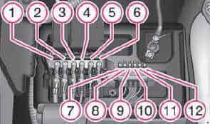
| Position | Rating [A] | Protected circuit / function |
|---|---|---|
| 1 | 175 | Alternator charging cable |
| 2 | 110 | Main passenger compartment power feed |
| 3 | 40 | Radiator cooling fan |
| 4 | 40 | ABS, TCS or ESP system |
| 5 | 50 | Power steering |
| 6 | 50 | Diesel glow plugs, footnote a |
| 7 | 25 | ABS, TCS or ESP additional feed |
| 8 | 30 | Radiator cooling fan auxiliary circuit |
| 9 | 5 | Air conditioning system |
| 10 | 15 | Engine Control Unit (ECU) |
| 11 | 5 | Central electronic controller |
| 12 | 5 | Automatic transmission |
Fabia I 12 V socket, wiper, fuel pump and starting faults
If the cigarette lighter fails, first disconnect chargers and check interior fuse 42 (15 A), then inspect the socket for a short circuit. If the front wipers stop, check interior fuse 41 (20 A); for the rear wiper check 32 (10 A) and the wiring at the tailgate.
If the petrol engine will not start, cabin fuse 61 (15 A) is associated with its fuel pump. Also check battery voltage, ignition and engine management, not just a single fuse. The battery-top high-current fuse for electric steering is position 3 in the 16-slot block or 5 in the 12-slot block; choosing the wrong chart can lead to incorrect service.
For an older model, see the Škoda Felicia (1994-2001) fuse diagram, whose passenger-side relay panel is completely different. For a later small Škoda with a different electrical panel, see the Škoda Citigo (2012) and Škoda Scala (2019-2020). Their fuse diagrams are not substitutes for the first-generation Fabia.
Škoda Fabia I 1999-2007 fuse FAQ
Where is the cigarette lighter fuse?
Cabin fuse 42, 15 A.
Are there always 68 fuses installed?
No. There are 68 numbered cabin positions, but unused sockets depend on equipment and engine.
Which fuse controls the rear wiper?
Cabin position 32 (10 A) in this original first-generation layout.
Why are there two different battery fuse diagrams?
Fabia I uses a 16-position or 12-position high-current block depending on version. They have different numbering for power steering, cooling and diesel glow plugs.
Is the 2007 Fabia always first generation?
No. Fabia II also debuted in 2007. Check whether the dashboard fuse panel has 68 (Fabia I) or 58 (Fabia II) positions and compare the actual fuse lid.
Use the exact type and amperage printed on the vehicle’s fuse cover or owner’s handbook. Never replace a fuse with a higher-rated one to stop repeated blowing.