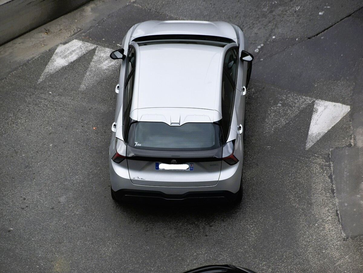
The MG4 EV, also sold as MG4 Electric, has two main low-voltage fuse boxes, one behind the driver’s lower dashboard trim and the other beneath the front bonnet. The following 2022-2025 MG4 fuse guide preserves the manufacturer’s F1-F46 passenger-compartment positions, F1-F93 front-compartment positions and the high-current fuses A-H.
The exact panel layout depends on production year, Standard/Comfort/Luxury/Trophy or XPower trim, rear- or all-wheel drive, towing provisions and other equipment. Many positions are unused in the documented first-generation configuration. They are retained in the tables to make the numbering match the diagrams. Later MG4 versions may differ, so use the vehicle’s own fuse label.
Where are the MG4 fuse boxes?
There are two accessible low-voltage distribution points: the cabin fuse panel under the lower driver’s side knee trim, and the front power distribution box on the left-hand side beneath the bonnet. Switch the vehicle off before opening an ordinary fuse cover.
| Box | Location | Fuse positions |
|---|---|---|
| Passenger compartment | Behind the lower dashboard/knee panel on the driver’s side | F1-F46 |
| Front compartment | Left side of the front compartment beneath a secured cover | F1-F93 oraz A-H |
These fuse panels do not authorise work on the high-voltage traction battery. Avoid orange cables and sealed high-voltage equipment; high-current distribution and battery electronics require suitably trained technicians.
MG4 Electric passenger-compartment fuse panel F1-F46
The cabin panel protects the heated steering wheel, charge-port controls, infotainment and display, driver seat, airbags, OBD diagnostic connector, 12 V socket, rear USB and wireless phone charger. In this original specification many positions F26-F43 are unoccupied.
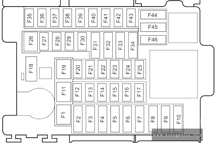
| Position | Amperage [A] | Protected circuit / function |
|---|---|---|
| F1 | – | – |
| F2 | 5 A | High-voltage electric heater control |
| F3 | 7.5 A | Gateway communication module |
| F4 | 15 A | Heated steering wheel |
| F5 | 5 A | Driver door switches, exterior mirrors, headlight levelling, electric parking brake (EPB), infotainment controls and steering wheel clock spring |
| F6 | 5 A | Pedestrian warning sound module and communications module |
| F7 | 5 A | Drive mode/gear selector and instrument cluster |
| F8 | 7.5 A | Digital radio, central display and front camera |
| F9 | 5 A | Vehicle charging port |
| F10 | – | – |
| F11 | 30 A | Driver seat adjustment controller and switch |
| F12 | – | – |
| F13 | 5 A | Driver fatigue monitoring module |
| F14 | 10 A | Airbag control module |
| F15 | 15 A | Superlock / additional central locking |
| F16 | – | – |
| F17 | – | – |
| F18 | 10 A | Electronic steering column lock |
| F19 | – | – |
| F20 | 10 A | DLC / OBD diagnostic connector |
| F21 | – | – |
| F22 | 10 A | Automatic climate control |
| F23 | – | – |
| F24 | 20 A | Main infotainment system module |
| F25 | 5 A | Rear driver assistance radar |
| F26 | – | – |
| F27 | – | – |
| F28 | – | – |
| F29 | – | – |
| F30 | – | – |
| F31 | – | – |
| F32 | – | – |
| F33 | – | – |
| F34 | – | – |
| F35 | – | – |
| F36 | – | – |
| F37 | – | – |
| F38 | – | – |
| F39 | – | – |
| F40 | – | – |
| F41 | – | – |
| F42 | – | – |
| F43 | – | – |
| F44 | 15 A | Front centre-console 12 V accessory power socket |
| F45 | 5 A | Rear USB port and wireless phone charging module |
| F46 | – | – |
MG4 Electric front compartment fuse box F1-F93
This panel protects the body controller, headlights, heated rear window, electric parking brake, traction and battery cooling pumps, windscreen wipers, heat pump and integrated charging controller. The factory chart lists unused positions F2-F50, with the allocated circuits appearing again from F51 onward.
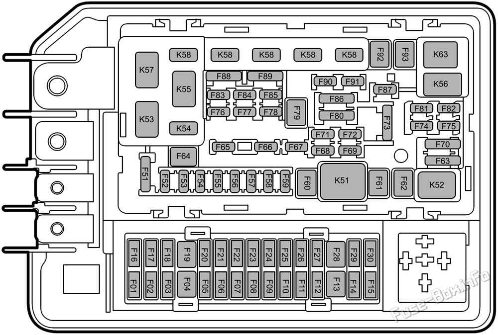
| Position | Amperage [A] | Protected circuit / function |
|---|---|---|
| F1 | 20 A | Reserved feed for towing/trailer electrics |
| F2 | – | – |
| F3 | – | – |
| F4 | – | – |
| F5 | – | – |
| F6 | – | – |
| F7 | – | – |
| F8 | – | – |
| F9 | – | – |
| F10 | – | – |
| F11 | – | – |
| F12 | – | – |
| F13 | – | – |
| F14 | – | – |
| F15 | – | – |
| F16 | – | – |
| F17 | – | – |
| F18 | – | – |
| F19 | – | – |
| F20 | – | – |
| F21 | – | – |
| F22 | – | – |
| F23 | – | – |
| F24 | – | – |
| F25 | – | – |
| F26 | – | – |
| F27 | – | – |
| F28 | – | – |
| F29 | – | – |
| F30 | – | – |
| F31 | – | – |
| F32 | – | – |
| F33 | – | – |
| F34 | – | – |
| F35 | – | – |
| F36 | – | – |
| F37 | – | – |
| F38 | – | – |
| F39 | – | – |
| F40 | – | – |
| F41 | – | – |
| F42 | – | – |
| F43 | – | – |
| F44 | – | – |
| F45 | – | – |
| F46 | – | – |
| F47 | – | – |
| F48 | – | – |
| F49 | – | – |
| F50 | – | – |
| F51 | 15 A | Horn relay circuit |
| F52 | 5 A | Electric Vehicle Communication Controller (EVCC) and active air intake shutter |
| F53 | 20 A | Left headlamp assembly |
| F54 | 30 A | Body Control Module (BCM) |
| F55 | 30 A | Body Control Module (BCM) |
| F56 | 5 A | Front radar |
| F57 | 5 A | Electric parking brake motor controller |
| F58 | 30 A | Body Control Module (BCM) |
| F59 | – | – |
| F60 | 30 A | Heated rear window |
| F61 | 40 A | Integrated braking system |
| F62 | 30 A | Power window motor |
| F63 | 5 A | Airbag controller, collision power module, instrument cluster, gateway, parking sensors and BCM |
| F64 | 30 A | Collision Power Module |
| F65 | – | – |
| F66 | 10 A | Electric exterior mirrors |
| F67 | – | – |
| F68 | 20 A | Electric parking brake motor controller |
| F69 | 30 A | Collision Power Module |
| F70 | 5 A | Integrated brake system, electric power steering, second-axle motor controller and intelligent electronic control |
| F71 | – | – |
| F72 | 20 A | Right headlamp assembly |
| F73 | 5 A | Battery sensor and brake pedal switch |
| F74 | – | – |
| F75 | – | – |
| F76 | – | – |
| F77 | 15 A | Power electronics box (PEB) coolant pump |
| F78 | 20 A | High-voltage traction battery pack system control feed |
| F79 | 50 A | HVAC air inlet module/box |
| F80 | 10 A | Second-axle motor controller and intelligent electronics |
| F81 | 15 A | Power electronics box (PEB) coolant pump |
| F82 | – | – |
| F83 | 15 A | Traction battery coolant pump |
| F84 | – | – |
| F85 | 15 A | Front windscreen wiper motor |
| F86 | 15 A | Heat pump control module |
| F87 | 5 A | Integrated charging unit |
| F88 | 5 A | Electric air-conditioning compressor and battery heater |
| F89 | 5 A | Interior and exterior mirrors, headlamp levelling and left/right headlamps |
| F90 | – | – |
| F91 | 30 A | Body Control Module (BCM) |
| F92 | 25 A | Windscreen wiper relay circuit |
| F93 | 30 A | Automatic power window motor |
High-current protection A-H
The front assembly also contains eight lettered positions A-H. Only C, E, G and H have assigned functions in this source: electric power steering, cabin fuse box supply, cooling fan and integrated braking system. These high-current fuses are not regular user-replaceable blade fuses.
| Position | Amperage [A] | Protected circuit / function |
|---|---|---|
| A | – | – |
| B | – | – |
| C | 80 A | Electric power steering |
| D | – | – |
| E | 100 A | Passenger compartment fuse box supply |
| F | – | – |
| G | 60 A | Cooling fan power feed |
| H | 60 A | Integrated braking system |
Frequently checked MG4 fuses
The table below summarises important fuse positions. It repeats selected circuits from the full cabin and front-compartment lists for quicker reference; it does not describe an additional fuse box.
| System / accessory | Fuse | Rating | Box |
|---|---|---|---|
| Front centre-console 12 V power socket | F44 | 15 A | Passenger compartment |
| Rear USB port | F45 | 5 A | Passenger compartment |
| Wireless phone charger | F45 | 5 A | Passenger compartment |
| Infotainment system | F24 | 20 A | Passenger compartment |
| Central display and digital radio | F8 | 7.5 A | Passenger compartment |
| OBD/DLC diagnostic connector | F20 | 10 A | Passenger compartment |
| Heated steering wheel | F4 | 15 A | Passenger compartment |
| Charging port | F9 | 5 A | Passenger compartment |
| Left headlamp | F53 | 20 A | Front compartment |
| Right headlamp | F72 | 20 A | Front compartment |
| Heated rear window | F60 | 30 A | Front compartment |
| Front wiper motor | F85 | 15 A | Front compartment |
| Front wiper relay circuit | F92 | 25 A | Front compartment |
| Heat pump control unit | F86 | 15 A | Front compartment |
| Integrated charging unit | F87 | 5 A | Front compartment |
MG4 12 V socket, USB, infotainment and charge-port fuses
The centre-console 12 V power socket is protected by cabin F44 (15 A). MG specifies a maximum accessory load of 120 W at 12 V for the socket in this source configuration. The rear USB port and wireless phone charging share cabin F45 (5 A), so a failed USB charger may not involve F44.
Infotainment uses cabin F24 (20 A), the central display/radio F8 (7.5 A), and the OBD/DLC diagnostics F20 (10 A). The charging port control uses cabin F9 (5 A). Front-compartment F52 (5 A) supplies the EV communication controller, while F87 (5 A) protects the integrated charging unit auxiliary circuit.
These charging-control fuses are not the main protection of the high-voltage traction cable. A charging failure may involve communication, connector or module faults instead of a blown fuse.
MG4 relay-associated fuse circuits
The general 2022-2025 MG source does not list every relay in a separate assignment table. Two fuses are explicitly identified as supplying relay circuits: horn relay F51 (15 A) and windscreen wiper relay F92 (25 A), both in the front compartment. Confirm any individual relay position on the actual box cover.
| Position | Amperage [A] | Protected circuit / function |
|---|---|---|
| F51 | 15 A | Horn relay circuit |
| F92 | 25 A | Windscreen wiper relay circuit |
MG4 equipment and production-year differences
Standard, Comfort, Luxury, Trophy and XPower versions can have different electrical loads. In some later versions, positions unused in 2022-2025 were assigned to additional features. These tables should not be used for 2026 versions without checking that vehicle’s documentation.
For a compact electric crossover, see the BYD ATTO 3 fuse diagrams. For other European electric models with different electrical layouts, compare theRenault Megane E-Tech Electric, Volkswagen ID.3 and Kia EV6 CV fuse diagrams. Fuse positions are not transferable between vehicles.
MG4 Electric fuse box FAQ
Which fuse protects the 12 V centre-console socket?
Cabin fuse F44, rated 15 A, in the documented 2022-2025 layout.
Where are the rear USB and wireless charger fuses?
Both functions are listed under cabin position F45 (5 A).
What protects the windscreen wipers?
The front wiper motor uses front fuse F85 (15 A), with the associated wiper relay feed at F92 (25 A).
Can I reuse these fuse diagrams for an updated MG4?
Not without checking the specific model year and trim. Some later MG4 variants have different occupied positions.
Only replace ordinary low-voltage fuses with the same physical type and amperage. If a fuse blows repeatedly, investigate the fault rather than fitting a higher current rating.
Fuse positions and assignments: MG4 Electric 2022-2025 fuse documentation. Featured vehicle photograph: Charles / usf1fan2, Wikimedia Commons, CC BY 2.0.