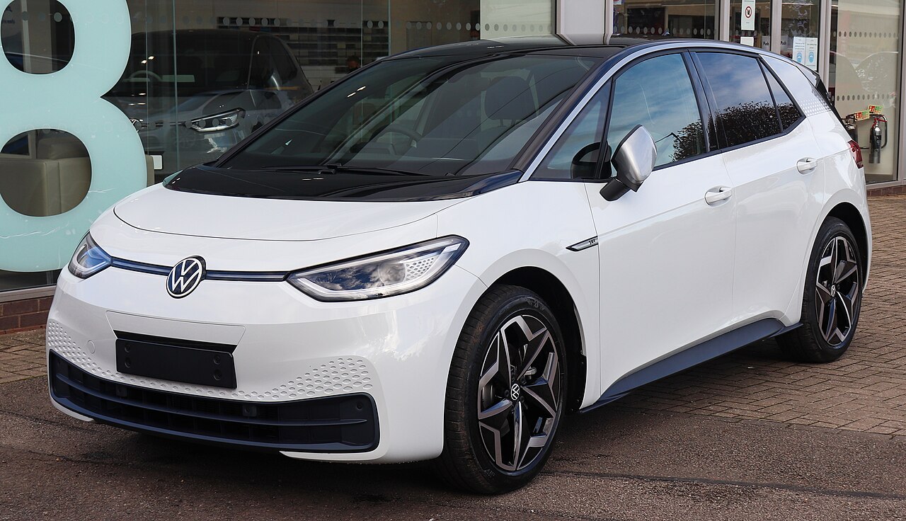
The Volkswagen ID.3 E11/E12 (2019-2023) has an under-bonnet SB fuse box, high-current SA power distribution and a dashboard SC panel. This guide lists the documented fuse positions, relays and driver-seat thermal fuses, preserving the original manufacturer’s designations and ratings.
Electrical equipment may differ by model year, country, trim and drivetrain specification. The diagrams below cover specified 2019-2023 layouts and are not a substitute for the label inside the fuse-box cover of your particular ID.3. Empty positions have been retained where they appear in the original table.
Electric vehicle safety: these lists describe low-voltage electrical protection, not a procedure for servicing traction battery equipment. Never open high-voltage enclosures or touch orange traction cables. High-current protection should be checked by an appropriately qualified technician.
Where are the fuse boxes in the Volkswagen ID.3?
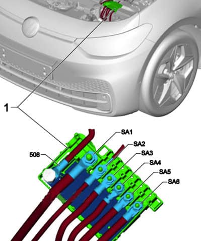
Front compartment: fuse box SB is beneath a clipped cover at the front of the car. The nearby SA distribution block provides high-current 12 V feeds to the voltage converter, steering system and main fuse panels. Switch off the vehicle before opening a user-accessible fuse box.
Passenger compartment: the SC box is behind the side cover at the left end of the dashboard in left-hand-drive vehicles. In right-hand-drive versions access may be behind a cover near the passenger glovebox. Check the label for the actual car.
Under-bonnet SB fuses and relays
The front SB panel supplies the ABS, electric drive control, headlamps, adaptive cruise control, air conditioning, radiator fan, electric brake assistance, acoustic warning system and windscreen wipers.
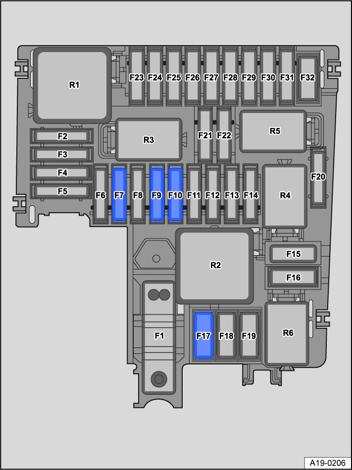
SB1-SB32 fuse assignments
| Position | Amperage [A] | Protected circuit / function |
|---|---|---|
| SB1 | – | Unoccupied position |
| SB2 | 7.5 | Anti-lock braking system (ABS) control unit |
| SB3 | 10 | Voltage converter and electric drivetrain power supply/control electronics |
| SB4 | 30 | Left front headlamp |
| SB5 | 30 | Right front headlamp |
| SB6 | 7.5 | Adaptive cruise control (ACC) |
| SB7 | 30 | Passenger-side front windscreen wiper motor |
| SB8 | – | Unoccupied position |
| SB9 | 15 | Horn |
| SB10 | 30 | Driver-side front windscreen wiper motor |
| SB11 | 7.5 | Air-conditioning relay |
| SB12 | 7.5 | Electric drive acoustic warning sound generator, module 1 |
| SB13 | 25 | Anti-lock braking system (ABS) control unit |
| SB14 | – | Unoccupied position |
| SB15 | 40 | Anti-lock braking system (ABS) control unit |
| SB16 | 50 | Engine bay radiator cooling fan |
| SB17 | 40 | Heated front windscreen |
| SB18 | – | Unoccupied position |
| SB19 | – | Unoccupied position |
| SB20 | – | Unoccupied position |
| SB21 | – | Unoccupied position |
| SB22 | – | Unoccupied position |
| SB23 | 10 | Electric drive motor control unit |
| SB24 | 5 | Cooling fan control |
| SB25 | 10 | High-voltage battery PTC heater coolant pump 3 |
| SB26 | 10 | Low-temperature circuit coolant pump and radiator shutter actuator |
| SB27 | – | Unoccupied position |
| SB28 | – | Unoccupied position |
| SB29 | – | Unoccupied position |
| SB30 | – | Unoccupied position |
| SB31 | – | Unoccupied position |
| SB32 | 50 | Brake servo assistance |
SB relays R1-R6
The original front-compartment layout identifies a main relay, a horn relay and an air-conditioning relay, with additional relay positions unoccupied in the documented configuration.
| Position | Amperage [A] | Protected circuit / function |
|---|---|---|
| R1 | – | Main power supply relay |
| R2 | – | Unoccupied relay position |
| R3 | – | Horn relay |
| R4 | – | Unoccupied relay position |
| R5 | – | Unoccupied relay position |
| R6 | – | Air-conditioning relay |
Common checks: SB7 (30 A) supplies the front passenger-side wiper motor, SB10 (30 A) the driver’s-side wiper motor and SB9 (15 A) the horn. The radiator cooling fan is assigned to SB16 (50 A), while SB24 (5 A) is associated with its control circuit.
High-current fuse panel SA
The SA block protects major auxiliary supply circuits including the voltage converter and steering control, along with feeds to the main dashboard and front-compartment fuse holders. It contains bolted high-current elements rather than ordinary replacement blade fuses.
| Position | Amperage [A] | Protected circuit / function |
|---|---|---|
| 508 | – | 12 V auxiliary battery connection, not a replaceable fuse |
| SA1 | 350 | Voltage converter |
| SA2 | 80 | Battery monitoring controller and electric power steering controller |
| SA3 | 100 | Fuse holder C, passenger compartment dashboard |
| SA4 | 100 | Fuse holder for cabin power distribution |
| SA5 | – | Unoccupied position |
| SA6 | 125 | Fuse holder B, front compartment |
SA1 is rated at 350 A, SA2 at 80 A, SA3 and SA4 at 100 A, and SA6 at 125 A in the documented layout. SA5 is unoccupied. Position 508 denotes the auxiliary battery connection and is not an ordinary fuse.
Dashboard SC fuses and relays
The SC panel protects airbags, safety belt pretensioners, exterior and interior lights, door electronics, infotainment, heating and air conditioning, connected-car equipment, USB sockets, 12 V power and rear window systems. The original SC numbering has been retained in full.
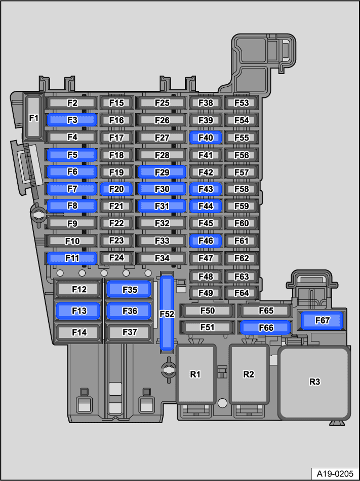
SC1-SC67 passenger compartment assignments
| Position | Amperage [A] | Protected circuit / function |
|---|---|---|
| SC1 | – | Unoccupied position |
| SC2 | 15 | Airbag control unit |
| SC3 | 25 | Trailer detection control unit |
| SC4 | 7.5 | Front camera for driver assistance systems |
| SC5 | 20 | Onboard power supply controller, left exterior lighting |
| SC6 | 30 | Onboard power supply controller, interior lighting |
| SC7 | 30 | Heating and air-conditioning control unit, including heated seats |
| SC8 | 15 | Sliding sunroof control unit |
| SC9 | 30 | Driver door controller and driver-side rear window regulator on LHD cars; front passenger door and opposite-side rear window controller on RHD cars |
| SC10 | 10 | Left rear lamp cluster |
| SC11 | 15 | Trailer detection control unit |
| SC12 | – | Unoccupied position |
| SC13 | 40 | Onboard electrical system control unit, central locking |
| SC14 | 30 | Digital sound system controller |
| SC15 | – | Unoccupied position |
| SC16 | – | Unoccupied position |
| SC17 | 5 | Park assist and lane-change assist controllers; door mirrors and lane-change warning indicators on the relevant LHD/RHD sides |
| SC18 | 5 | Smart-card reader, electronic steering lock, keyless entry/start interface and anti-theft protection control units |
| SC19 | 5 | Emergency call and communications control unit; driver information display controller |
| SC20 | 10 | Phone holder, signal transmission/reception stabilisation unit and USB connector 1 |
| SC21 | 7.5 | Tailgate latch/control and surround-view camera controller |
| SC22 | 10 | Electric drive motor control unit |
| SC23 | 5 | Internet access control module |
| SC24 | 10 | Right rear lamp cluster |
| SC25 | 25 | Left front seatbelt pretensioner |
| SC26 | 30 | Front passenger door and opposite-side rear window controllers on LHD cars; driver door and driver-side rear window controllers on RHD cars |
| SC27 | 25 | Right front seatbelt pretensioner |
| SC28 | 10 | Voltage converter, battery regulation control unit and high-voltage service connector control |
| SC29 | 15 | Trailer detection control unit |
| SC30 | 20 | Infotainment electronics control unit 1 |
| SC31 | 25 | Trailer detection control unit |
| SC32 | 25 | Onboard power supply control unit |
| SC33 | – | Unoccupied position |
| SC34 | 15 | Heating and air-conditioning controller |
| SC35 | 40 | Rear seat heater |
| SC36 | 40 | Fresh-air blower control unit |
| SC37 | – | Unoccupied position |
| SC38 | 7.5 | Left and right front-seat massage controllers |
| SC39 | 15 | Steering column electronics control unit |
| SC40 | 10 | Anti-theft alarm horn |
| SC41 | 5 | Vehicle data bus diagnostic interface |
| SC42 | – | Unoccupied position |
| SC43 | 7.5 | Interior CO2 sensor, cabin temperature sensor and heated rear-window relay |
| SC44 | 7.5 | Dashboard centre switch, window/lighting controllers, rain/light and alarm sensors, illuminated dashboard information strip, interior lighting and diagnostic connector |
| SC45 | 5 | Steering column electronics controller |
| SC46 | 10 | Information display and head-up display (HUD) control unit |
| SC47 | 10 | Electronically controlled damping controller, 2020-2022 |
| SC48 | 10 | USB charging socket 1 |
| SC49 | – | Unoccupied position |
| SC50 | – | Unoccupied position |
| SC51 | – | Unoccupied position |
| SC52 | 20 | 12 V accessory socket, circuit 3 |
| SC53 | – | Unoccupied position |
| SC54 | – | Unoccupied position |
| SC55 | – | Unoccupied position |
| SC56 | – | Unoccupied position |
| SC57 | – | Unoccupied position |
| SC58 | 7.5 | Smart-card reader controller |
| SC59 | 7.5 | Power outlet relay and auto-dimming interior mirror |
| SC60 | 7.5 | Diagnostic connection |
| SC61 | 5 | Electric drive supply and control electronics |
| SC62 | – | Unoccupied position |
| SC63 | – | Unoccupied position |
| SC64 | – | Unoccupied position |
| SC65 | – | Unoccupied position |
| SC66 | 15 | Rear windscreen wiper motor |
| SC67 | 30 | Heated rear window |
Cabin supply relays R1-R3
| Position | Amperage [A] | Protected circuit / function |
|---|---|---|
| R1 | – | 12 V accessory socket power supply relay |
| R2 | – | Terminal 15 voltage supply relay |
| R3 | – | Heated rear window relay |
Where are the USB, 12 V socket, wiper and horn fuses?
The documented ID.3 uses SC48 (10 A) for USB charging socket 1 and SC52 (20 A) for the 12 V accessory outlet circuit 3. The 12 V socket power relay is R1 in the cabin panel. The infotainment system controller is supplied by SC30 (20 A).
The front wipers are supplied by SB7 and SB10 (30 A each), with the horn at SB9 (15 A). The rear wiper uses SC66 (15 A) and rear window heating uses SC67 (30 A).
For a related MEB electric hatchback, compare the Cupra Born fuse box diagrams. For Volkswagen’s larger electric SUVs, use the Volkswagen ID.4 and ID.5 fuse diagrams. The Skoda Enyaq is another related MEB-based SUV, but its fuse assignments also differ. None of these diagrams should be substituted for another model’s cover labels.
Thermal fuses for driver’s power seat
Where the documented electric seat arrangement is fitted, the front-left and front-right driver seat adjustment thermal protection entries are both rated at 15 A. These are listed separately from the SC passenger-compartment panel.
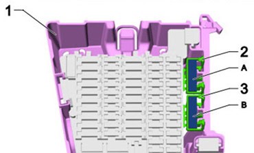
| Position | Amperage [A] | Protected circuit / function |
|---|---|---|
| A | 15 | Driver seat adjustment thermal fuse, front left |
| B | 15 | Driver seat adjustment thermal fuse, front right |
Different model years and MEB variants
Depending on country, left-hand/right-hand drive, equipment and updates within the 2019-2023 period, several circuits and slot occupants may differ. For example, the positions serving side-door window electronics and driver assistance should be verified against the precise vehicle configuration.
Only use the listed fuse amperage for the same equipment and fuse slot in the vehicle. If a replacement repeatedly blows, investigate the connected circuit rather than increasing the rating.
Volkswagen ID.3 fuse box FAQ
Where are the cabin fuses in a VW ID.3?
In the dashboard SC panel, behind the side trim on left-hand-drive cars. The right-hand-drive access arrangement can differ.
Which fuses supply the USB and 12 V sockets?
SC48 is rated at 10 A for USB charging, while SC52 is 20 A for the third 12 V accessory outlet circuit in the documented layout.
Which fuses protect the wipers and horn?
Under the front cover, SB7 and SB10 each carry 30 A for the front wipers, while SB9 is the 15 A horn fuse. In the cabin, SC66 is 15 A for the rear wiper.
Can I use these tables for later ID.3 versions?
Not without confirming the vehicle’s fuse-panel diagram and service documentation. Equipment revisions can change the layout. Never access orange high-voltage wiring during ordinary fuse checks.
Main vehicle photograph: Vauxford, Wikimedia Commons, CC BY-SA 4.0, photograph used unchanged. Fuse assignments: Volkswagen ID.3 E11/E12 2019-2023 SB, SA and SC documentation.