
Dacia Duster I (2010-2016) is the original generation of the budget SUV built with Renault Group components. This guide details the complete 39-position passenger compartment fuse panel, supplementary relay 750 and two separate petrol engine fuse and relay layouts for the 1.6 16V K4M and 2.0 16V F4R. The F4R version was sold mainly in selected markets outside Poland. Do not apply its engine fuse diagram to a European 1.5 dCi diesel without verifying the installed hardware.
In the technical arrangement below, F38 (15 A) protects the front cigarette lighter, 12 V accessory outlet and radio. F36 (30 A) powers the cabin blower, F1 (20 A) the front wipers and F34 (15 A) the 4×4 torque distribution ECU. Fuse assignments can still differ by build date, engine code, market and equipment, so the fuse box legend and VIN-matched documentation are decisive.
Where are the Dacia Duster I fuse boxes?
In the passenger compartment: open the driver’s door and look at the lower side of the dashboard, to the left of the steering column in left-hand-drive cars. The panel sits behind a removable plastic access cover. Switch off the ignition, release the cover at the point shown in the illustration and compare its interior fuse legend with the actual slots. The Dacia 2012 handbook calls this panel A. Use the factory plastic fuse puller if one is provided. Clip the cover fully back into place after inspection.
Under the bonnet: there are supplementary fuse and relay modules near the battery and engine management ECU. Switch off the engine, apply the parking brake and open the bonnet. Identify the relevant box and remove only its accessible cover. High-current fuses and internal relays can require removal of other components and electrical isolation; the manufacturer recommends workshop service for difficult-to-reach under-bonnet protections.
Supplementary equipment: depending on the engine and options, relays can carry identifiers 299, 233, 1047, 784, 336, 1639 or 232. These are not extra cabin fuse positions. Some FlexFuel models have an additional fuel pump, and 4×4 versions have a separate torque distribution controller.
Passenger compartment fuse box F1-F39 and relay 750
The diagram identifies the 39 cabin fuse positions. Some handbook editions label them 1-39 plus accessory locations A-C, while service information may use F1-F39. Match the drawing to the exact panel; a number on one carrier is not proof that another carrier serves the same circuit. Relay 750 (40 A) operates the rear electric window child safety lock and is included at the end of the table so no position is lost.
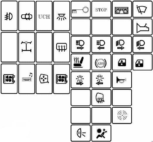
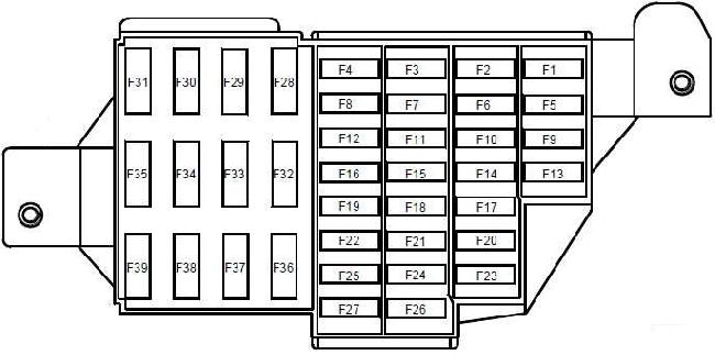
| Position | Amperage [A] | Protected circuit / function |
|---|---|---|
| F1 | 20 | Front windscreen wiper motor, combined washer/wiper switch and UCH body module |
| F2 | 5 | Instrument cluster, fuel pump relay control and injection ECU |
| F3 | 10 | Brake light switch |
| F4 | 10 | UCH body control module, OBD diagnostic port, immobiliser transponder and antitheft system |
| F5 | 5 | Automatic gearbox control, starter relay and 4WD torque distribution ECU – variant-dependent |
| F6 | – | Unoccupied in the described electrical layout |
| F7 | – | Unoccupied in the described electrical layout |
| F8 | – | Unoccupied in the described electrical layout |
| F9 | 10 | Left dipped-beam headlamp and cluster indication |
| F10 | 10 | Right dipped-beam headlamp |
| F11 | 10 | Left main-beam headlamp and cluster warning lamp |
| F12 | 10 | Right main-beam headlamp |
| F13 | 30 | Driver and rear window controls and anti-trap feature |
| F14 | 30 | Driver-side front electric window control |
| F15 | 10 | ABS control unit |
| F16 | 15 | Radio |
| F17 | 15 | Main and supplementary horns |
| F18 | 10 | Left front and rear position lamps |
| F19 | 10 | Right position lamps, cabin and number-plate lights, UCH, instrument cluster, climate control panel, radio, 4WD controls, switch backlighting and lighter control circuits |
| F20 | 7.5 | Rear fog light |
| F21 | 5 | Instrument cluster |
| F22 | – | Unoccupied in the described electrical layout |
| F23 | 15 | Horn power through relay, on factory alarm-equipped versions |
| F24 | – | Unoccupied in the described electrical layout |
| F25 | – | Unoccupied in the described electrical layout |
| F26 | 5 | SRS airbag and seat-belt pretensioner ECU |
| F27 | 20 | Rear wiper/washer, reversing lights, reverse/neutral gear sensor, automatic gearbox control and parking sensors – equipment-dependent |
| F28 | 15 | Ignition-switched consumer feed, instrument cluster, radio and UCH |
| F29 | 15 | UCH body control, OBD diagnostic supply and antitheft ECU |
| F30 | 20 | UCH central body electronics |
| F31 | 15 | Front fog lamps, their relay and cluster indicator |
| F32 | 30 | Heated rear window switch |
| F33 | – | Unoccupied in the described electrical layout |
| F34 | 15 | Four-wheel-drive torque distribution control ECU – 4×4 versions only |
| F35 | – | Unoccupied in the described electrical layout |
| F36 | 30 | Cabin ventilation blower motor, relay and A/C control panel |
| F37 | 5 | Left and right electric mirror adjustment |
| F38 | 15 | Radio and front cigarette lighter / 12 V accessory socket |
| F39 | 10 | Cabin blower relay control supply |
| 750 | 40 | 750: rear electric window child safety lock relay, supplementary unit low in dashboard |
Engine fuse and relay box – petrol K4M 1.6 16V
The K4M690 and K4M694 arrangements use fuse modules 597-1 through 597-5 together with separate relay carriers. Here 1-F1 means position F1 in block 597-1; 2-F1 means F1 in 597-2. The prefix is essential because there are several unrelated F1 slots.
Examples include non-ESP ABS supply at 597-1 F1 (50 A) and F2 (25 A), cooling fan 597-2 F1 (40 A), cabin supply 597-3 F1 and F2 (60 A each), and injection/fuel pump feed 597-5 F2 (25 A). Relays 299, 1047 and 784 control functions including the horn, fuel pump, air conditioning and radiator fan.
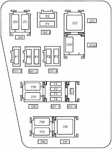
| Position | Amperage [A] | Protected circuit / function |
|---|---|---|
| 1-F1 | 50 | 597-1: ABS controller without ESP, first 50 A supply |
| 1-F2 | 25 | 597-1: ABS controller without ESP, second 25 A supply |
| 2-F1 | 40 | 597-2: radiator fan feed via low/high speed relays and resistor; includes A/C compressor clutch on equipped versions |
| 3-F1 | 60 | 597-3: ignition switch and passenger compartment fuse F23 feed |
| 3-F2 | 60 | 597-3: cabin electrical supply, including F29 and F36 |
| 4-F1 | – | 597-4: unused in the illustrated layout |
| 4-F2 | 25 | 597-4: feed to cabin F34 four-wheel-drive controller circuit |
| 5-F1 | 30 | 597-5: cooling fan low-speed relay, basic heater configuration |
| 5-F2 | 25 | 597-5: injection cut-off and fuel pump relay power supply |
| 5-F3 | – | 597-5: unoccupied fuse position |
| 5-F4 | – | 597-5: unoccupied fuse position |
| 597-6 | – | 597-6: protective diode for A/C compressor clutch circuit |
| 299-A | 20 | 299: front fog lamp relay |
| 299-B | 20 | 299: horn relay |
| 233 | 40 | 233: passenger compartment blower motor relay |
| 1047-A | 20 | 1047: fuel injection cut-off relay |
| 1047-B | 20 | 1047: fuel pump relay |
| 784-A | 20 | 784: radiator fan low-speed relay |
| 784-B | 20 | 784: air-conditioning compressor clutch relay |
| 336 | 40 | 336: radiator fan high-speed relay |
| 1639-A | – | 1639: unoccupied relay position on FlexFuel version |
| 1639-B | 20 | 1639: supplementary fuel pump relay on FlexFuel version |
Engine fuse and relay box – petrol F4R 2.0 16V
F4R400, F4R402, F4R403, F4R404, F4R405 and F4R408 engines can have a similar assembly with important circuit differences. The key change is 597-5 F1: on the K4M layout it is 30 A for the cooling fan with basic heating, while on the F4R arrangement it is 15 A for the air-conditioning compressor clutch. In F4R403 and F4R405 four-speed automatic versions, 597-5 F4 (15 A) protects the gearbox controller, with starter relay 232 (40 A) also fitted.
The table retains each unused slot and the FlexFuel variant. A 1639-B relay is associated with an additional fuel pump on those cars; the corresponding position can be unoccupied on other versions. This engine diagram is not a substitute for the correct 1.5 dCi or Duster II wiring.
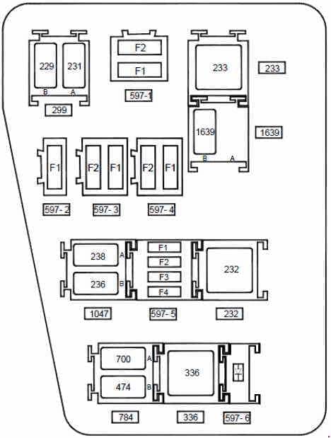
| Position | Amperage [A] | Protected circuit / function |
|---|---|---|
| 1-F1 | 50 | 597-1: ABS controller without ESP, first 50 A supply |
| 1-F2 | 25 | 597-1: ABS controller without ESP, second 25 A supply |
| 2-F1 | 40 | 597-2: radiator fan feed via low/high speed relay and resistor – air-conditioned configuration |
| 3-F1 | 60 | 597-3: ignition switch and passenger compartment F23 feed |
| 3-F2 | 60 | 597-3: cabin electrical supply, including F29 and F36 |
| 4-F1 | – | 597-4: unused in the illustrated layout |
| 4-F2 | 25 | 597-4: feed to cabin F34 four-wheel-drive controller circuit |
| 5-F1 | 15 | 597-5: A/C compressor clutch power via relay – air-conditioned variant |
| 5-F2 | 25 | 597-5: injection cut-off and fuel pump relay supply |
| 5-F3 | – | 597-5: unoccupied fuse position |
| 5-F4 | 15 | 597-5: four-speed automatic transmission controller on F4R403 / F4R405 |
| 597-6 | – | 597-6: protective diode for A/C compressor clutch circuit |
| 299-A | 20 | 299: front fog lamp relay |
| 299-B | 20 | 299: horn relay |
| 233 | 40 | 233: passenger compartment blower motor relay |
| 1047-A | 20 | 1047: fuel injection cut-off relay |
| 1047-B | 20 | 1047: fuel pump relay |
| 784-A | 20 | 784: radiator fan low-speed relay |
| 784-B | 20 | 784: air-conditioning compressor clutch relay |
| 336 | 40 | 336: radiator fan high-speed relay |
| 232 | 40 | 232: starter relay – automatic gearbox version only |
| 1639-A | – | 1639: unoccupied relay position on FlexFuel version |
| 1639-B | 20 | 1639: supplementary fuel pump relay on FlexFuel version |
Variations by year, market, drivetrain and engine
The earliest Dusters predate the facelift, while later cars received changes to body equipment and engine control systems. Wiring depends on the actual engine code, 4×2 or 4×4 drivetrain, air conditioning, manual or automatic transmission, and export market. Factory LPG or aftermarket gas systems may have separate fuses near the battery or gas valves, outside the standard petrol layouts shown here.
The Dacia Duster 2012 owner’s handbook shows cabin slots 1-39 and positions A-C. More detailed workshop material uses F1-F39 and under-bonnet modules 597. These identifiers should be compared rather than assumed interchangeable. A diesel 1.5 dCi requires a matching engine-bay diagram that is not covered by the two petrol tables in this article.
Duster I electrical faults – useful checks
Front cigarette lighter or 12 V outlet has no power: check cabin F38 (15 A) in the described technical configuration. If the radio still works, inspect the socket for damaged contacts or fragments of a charger adapter before installing another fuse. Never increase the rating to overcome a recurring short circuit.
Front wipers are not operating: F1 (20 A) protects the wiper motor and the related switch/UCH circuits. If the blades work but the washer does not spray, also inspect the washer pump, reservoir wiring and frozen fluid.
No cabin ventilation: F36 (30 A) supplies the blower, F39 (10 A) its relay control, and engine bay relay 233 (40 A) is also part of the system. A blower functioning only at the maximum speed often points to its resistor or speed regulator.
Four-wheel drive will not engage: on a 4×4 car check cabin F34 (15 A). For the listed petrol K4M/F4R modules, 597-4 F2 (25 A) also feeds the controller. A blinking 4WD warning can instead indicate an electromagnetic coupling or wiring problem, so electronic diagnosis may be needed.
Heated rear window is inoperative: F32 (30 A) supplies the rear-window heater switch in the listed layout. Inspect the glass heating tracks and the wiring through the tailgate, particularly for intermittent faults.
Engine will not start or fuel pump is silent: on K4M/F4R petrol versions, 597-5 F2 (25 A) and relays 1047-A and 1047-B supply injection and fuel pump controls. Check battery voltage, immobiliser and ECU trouble codes first. Never bridge a relay or replace a fuse with wire.
Related Dacia models and technical references
The Duster I shares part of its B0 electrical architecture with the Dacia Logan I and Dacia Sandero I. Their fuse numbers should not be copied into a Duster without matching the installed module.
References: Dacia Duster 2012 owner’s handbook fuse section and workshop fuse/relay documentation for K4M and F4R engines. Consult the box legend and VIN-specific manufacturer documentation before fitting a replacement.