
Dacia Sandero I B90 (2008-2012) is the first generation of Dacia’s compact hatchback, built on the B0 platform shared with the Logan. European cars commonly came with 1.4 and 1.6 petrol engines, the 1.6 16V, 1.5 dCi diesel or factory LPG. Sandero Stepway I shares much of its mechanical base, but optional equipment can change electrical assignments.
The main fuse boxes are behind the driver’s-side dashboard end cover and under the bonnet near the battery. At least three different engine-bay layouts are documented: a K4M/K7M petrol version, a high-current box found on diesel configurations, and a 597A/597B distribution arrangement on some K7J petrol models. These are distinct installations, not different views of one universal box. Identify the engine code and the actual hardware before selecting a fuse.
Dacia Sandero I fuse box locations and access
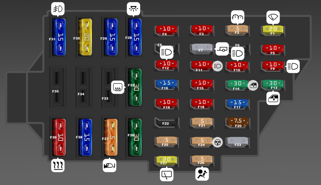
Passenger compartment: on left-hand-drive cars, the main fuse carrier is on the driver’s-side end of the dashboard, accessible with the door open. Switch off the ignition and accessories, open the driver’s door, grip the cover indentation and gently unclip the plastic panel. Read the fuse positions and amp ratings from the diagram inside the cover. A plastic fuse puller and spare fuses may also be stored there. Access on right-hand-drive cars can be different.
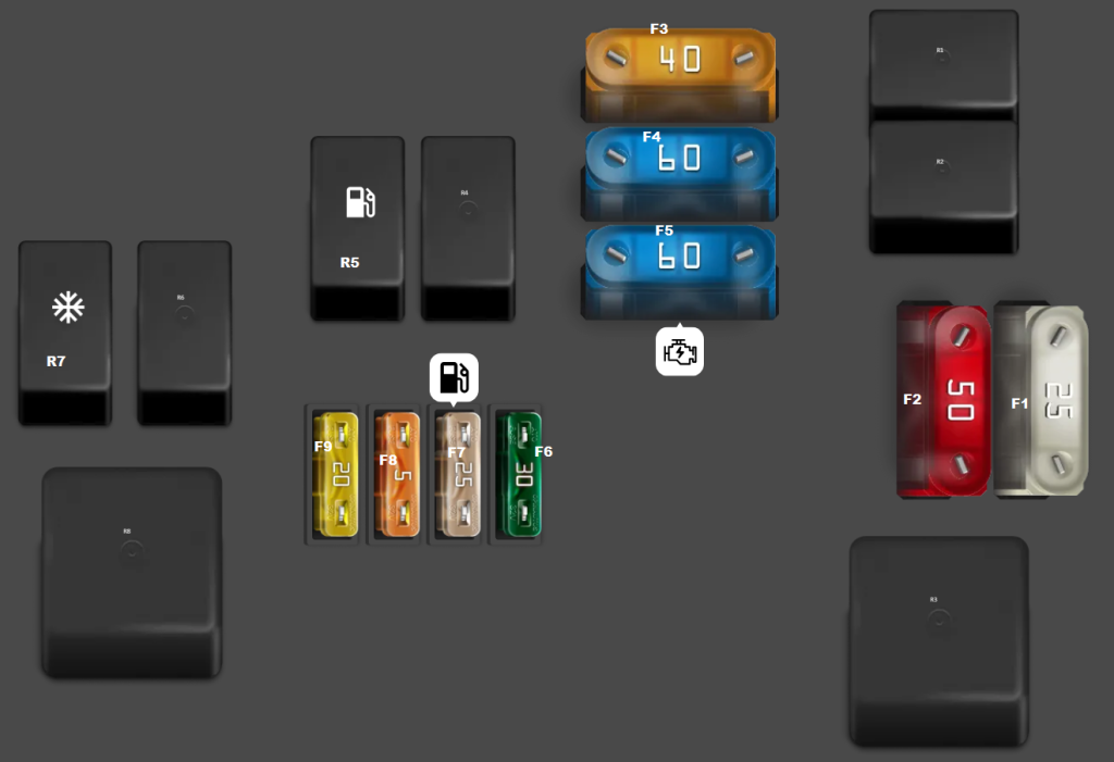
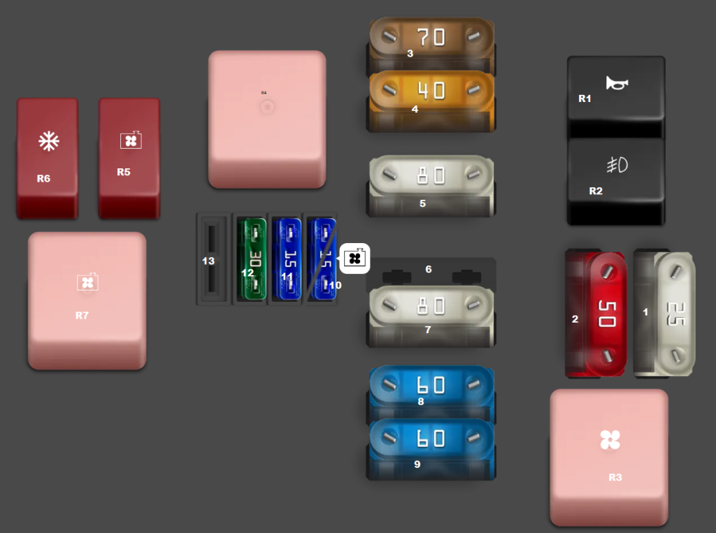
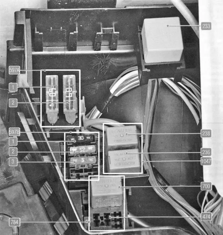
Engine bay: with the engine and ignition off, open the bonnet and find the fuse box alongside the battery, below a plastic cover. Release the clips and compare the physical carrier with the three diagrams in this article. A 1.4 petrol, 1.6 petrol and 1.5 dCi diesel can use different relays and high-current links. Some MAXI fuses are difficult to access and are intended to be serviced professionally.
Passenger compartment – all F1-F39 positions
There are 39 physical cabin fuse positions, including unused F6, F8, F22 and F33-F35 in the illustrated installation. F7 can be provided for factory trailer wiring and F23 for an antitheft alarm. Alternative documented ratings for F3, F19, F32, F38 and F39 are retained on separate rows, rather than silently selecting one version.
Radio and cigarette lighter: position F38 can serve the radio and accessory outlet. The later illustrated arrangement specifies 15 A, while earlier service documentation also lists a 10 A option. Confirm the cover’s assigned position and rating before installing a replacement fuse.
| Position | Amperage [A] | Protected circuit / function |
|---|---|---|
| F1 | 20 | Front windscreen wipers and heated rear-window relay control supply |
| F2 | 5 | Instrument cluster, engine ECU and injection relay control circuit |
| F3 | 10 | Brake pedal sensor and reversing-light switch – version found on many vehicles from 2009 onwards |
| F3 | 20 | Brake pedal sensor and reversing-light switch – alternative earlier wiring version |
| F4 | 10 | Engine immobiliser, SRS airbags and seat-belt pretensioner control, depending on equipment |
| F5 | 10 | Automatic transmission control – equipped versions only |
| F6 | – | Spare socket with no assigned circuit in the illustrated layout |
| F7 | – | Provision for factory trailer wiring, if fitted |
| F8 | – | Unused position / spare |
| F9 | 10 | Left dipped-beam headlamp |
| F10 | 10 | Right dipped-beam headlamp |
| F11 | 10 | Left high-beam headlamp and main-beam indicator |
| F12 | 10 | Right high-beam headlamp |
| F13 | 30 | Rear electric windows, if fitted |
| F14 | 30 | Front electric windows |
| F15 | 10 | ABS control unit |
| F16 | 15 | Heated front seats, if equipped |
| F17 | 15 | Horn |
| F18 | 10 | Left position lamp, number plate light, hazard-light control and selected accessories |
| F19 | 10 | Right position lamps – 10 A version |
| F19 | 7.5 | Right position lamps – earlier 7.5 A service-documentation version |
| F20 | 7.5 | Rear fog lamp and its control circuit |
| F21 | 5 | Heated exterior mirrors, if fitted |
| F22 | – | Unused position / spare |
| F23 | – | Reserved for antitheft alarm, if fitted |
| F24 | 5 | Power steering control circuit, depending on equipment |
| F25 | 5 | Factory LPG fuel system supply, if equipped |
| F26 | 5 | Separate airbag and belt pretensioner ECU control supply |
| F27 | 20 | Rear window wiper and selected reversing-light circuits |
| F28 | 15 | Cabin and luggage-compartment lights, permanent radio feed on selected versions |
| F29 | 15 | Comfort circuits, hazard lights and body-control electronics |
| F30 | 20 | Central locking, door and tailgate lock control |
| F31 | 15 | Front fog lamps and their relay control |
| F32 | 30 | Heated rear window – 30 A layout shown in diagram |
| F32 | 20 | Heated rear window – alternative 20 A service-documentation layout |
| F33 | – | Unused position / spare |
| F34 | – | Unused position / spare |
| F35 | – | Unused position / spare |
| F36 | 30 | Cabin blower and heating, including air-conditioned versions |
| F37 | 5 | Electric exterior mirror adjustment |
| F38 | 15 | Radio and accessory feed – 15 A newer illustrated version |
| F38 | 10 | Radio and cigarette lighter/accessory feed – alternative 10 A older installation |
| F39 | 10 | Blower, heating and A/C control – 10 A layout |
| F39 | 30 | Blower supply – alternative 30 A older service configuration |
Engine compartment type 1 – K4M/K7M petrol engines
This installation used on selected K4M and K7M petrol cars has nine fuse positions F1-F9 and eight relays R1-R8. F1 and F2 supply ABS, F3 is associated with radiator cooling, F4 and F5 distribute main battery power, and F7/F8 protect injection and fuel pump controls. F9 is provided for particular automatic transmission configurations and may be empty on manual cars.
| Position | Amperage [A] | Protected circuit / function |
|---|---|---|
| F1 | 25 | ABS module – power circuit 1 |
| F2 | 50 | ABS module – power circuit 2 |
| F3 | 40 | Radiator fan and A/C compressor clutch relay supply |
| F4 | 60 | Main electrical accessory and cabin fuse panel feed |
| F5 | 60 | Ignition switch, lighting and passenger-compartment circuits, including market-dependent daytime lights |
| F6 | 30 | Engine management and relay carrier power supply |
| F7 | 25 | Fuel pump and injection cut-off relay supply |
| F8 | 5 | Injection ECU and injection cut-off relay control |
| F9 | 20 | Automatic transmission controller, only on relevant K4M versions |
| R1 | – | Front fog light relay |
| R2 | – | Horn relay |
| R3 | – | Blower / air ventilation relay |
| R4 | – | Fuel injection cut-off relay |
| R5 | – | Fuel pump relay |
| R6 | – | Radiator cooling fan first-speed relay |
| R7 | – | Air-conditioning compressor clutch relay |
| R8 | – | Radiator cooling fan high-speed relay |
Engine compartment type 2 – high-current fuses, including 1.5 dCi
This alternative carrier contains larger fuses and a different set of relays. Position 3 (70 A) protects the diesel glow-plug controller. Other specified functions include 80 A power steering, 80 A auxiliary heating, a 60 A main cabin supply and cooling fan and air-conditioning relays. Positions 6 and 13 are unused in the depicted box.
Position 10 has a 15 A or 30 A alternative for the radiator fan low-speed control circuit; the pictured diagram corresponds to the 15 A configuration. Do not select the higher rating solely because another 1.5 dCi uses it.
| Position | Amperage [A] | Protected circuit / function |
|---|---|---|
| 1 | 25 | ABS ECU – first high-current fuse |
| 2 | 50 | ABS ECU – second high-current fuse |
| 3 | 70 | Diesel glow-plug controller |
| 4 | 40 | A/C compressor and cooling fan first/second-speed relay supply |
| 5 | 80 | Power steering pump on equipped versions |
| 6 | – | Unused in the illustrated box |
| 7 | 80 | Auxiliary heating relays, depending on diesel equipment |
| 8 | 60 | Main cabin fuse box power feed |
| 9 | 60 | Ignition switch and daytime running light supply, if fitted |
| 10 | 15 | Cooling fan low-speed control supply – 15 A version |
| 10 | 30 | Cooling fan control – alternative 30 A wiring variant |
| 11 | 15 | Mass air flow sensor and diesel fuel water detection sensor |
| 12 | 30 | Diesel fuel-injection ECU supply |
| 13 | – | Unused in the illustrated box |
| R1 | – | Horn relay |
| R2 | – | Front fog lamp relay |
| R3 | – | Cabin heater fan relay |
| R4 | – | Diesel fuel injection controller relay |
| R5 | – | Radiator fan low-speed relay |
| R6 | – | Air-conditioning compressor clutch relay |
| R7 | – | Radiator fan high-speed relay |
Alternative petrol K7J blocks – 597A and 597B
On some 1.4 K7J engines, separate modules labelled 597A, 597B, 784 and 1047 replace the F1-F9 scheme above. The two 597A main feeds are each 60 A. Block 597B includes circuits rated 30, 25 and 5 A. Relay 236 is for the fuel pump, relay 238 for injection cut-off, and 233 for the passenger-compartment blower. These component labels must not be converted into fuse positions from the other engine boxes.
| Position | Amperage [A] | Protected circuit / function |
|---|---|---|
| 597A/1 | 60 | 597A/1: ignition switch, exterior light switch and daytime running light relay feed |
| 597A/2 | 60 | 597A/2: lighting and passenger-compartment fuse box supply |
| 597B/1 | 30 | 597B/1: main relay carrier power feed |
| 597B/2 | 25 | 597B/2: injection relay power supply |
| 597B/3 | 5 | 597B/3: engine ECU and injection relay control circuit |
| 784/474 | 20 | 784/474: A/C compressor clutch relay circuit protection |
| 784/700 | 20 | 784/700: radiator cooling fan relay circuit protection |
| 1047/236 | – | 1047/236: fuel pump relay |
| 1047/238 | – | 1047/238: fuel injection cut-off relay |
| 233 | – | 233: separate cabin heater blower relay |
Production years, petrol/diesel and LPG variations
Before and after 2009: the factory service information gives alternatives for cabin F3, F19, F38, F39 and heated rear-window F32. In the later illustrated arrangement F3 is 10 A, F19 10 A, F32 30 A, F38 15 A and F39 10 A. However, these wiring changes did not necessarily occur on one fixed January date; production batch and market also matter.
Petrol and diesel: K7J, K7M and K4M engines can use separate fuse-and-relay modules. The 1.5 dCi has glow-plug and diesel injection circuits. A petrol Sandero will not need the same 70 A diesel glow-plug feed.
LPG: a factory gas system can use cabin F25 (5 A), while a later aftermarket installation often has additional fuse holders near its valves or the battery. Do not assume that every LPG conversion follows the original Dacia factory wiring.
Stepway I versus Sandero II: Stepway shares the first-generation platform but can differ in lights or options. The second-generation Sandero sold from late 2012 has another electrical installation, so check the generation as well as the year.
Dacia Sandero I – practical electrical checks
Radio or cigarette lighter is dead: inspect F38, which can be rated 10 or 15 A according to the installation. If the radio works but the socket does not, inspect the socket contacts and any separate accessory feed before replacing a good fuse. Damaged phone chargers can cause a direct short circuit.
One dipped-beam headlight is out: the cabin panel uses F9 (10 A) for the left and F10 (10 A) for the right. Main beams are separately protected by F11/F12 (10 A each). Check the bulb holder and earth point when a fuse tests good.
Wipers do not operate: check cabin F1 (20 A) for the front wipers and F27 (20 A) for the rear. Also examine wiring in the tailgate gaiter if the rear wiper and heated window both fail.
Heated rear window fails: inspect F32 (20 or 30 A, depending on the version) and the defogger relay. A partially working window usually calls for inspecting conductive glass tracks and the terminals.
Engine cranks without starting: in the K4M/K7M petrol box, fuse F7 (25 A) and F8 (5 A) protect injection control, while R5 is the fuel pump relay and R4 the injection cut-off relay. The K7J 597A/597B boxes use different labels. A faulty crankshaft position sensor can also cause a no-start condition.
No cabin blower: check F36 (30 A) and version-specific F39, then test the blower motor, resistor and relay. A blower working only on its highest setting often points to a failed resistor rather than a fuse.
Related Dacia models
Sandero I shares its B0 platform and much of its engineering with the Dacia Logan I (2005-2013). For the newer generation, see Dacia Sandero II (2012-2020). The layouts must be checked separately even where engines and components are related.
Technical references: Dacia Sandero I B90 2012 owner’s handbook, Sandero I workshop electrical documentation and comparisons for K7J, K7M, K4M and diesel variants. The actual fuse cover and the vehicle’s VIN-specific documentation take precedence if they differ from a general guide.