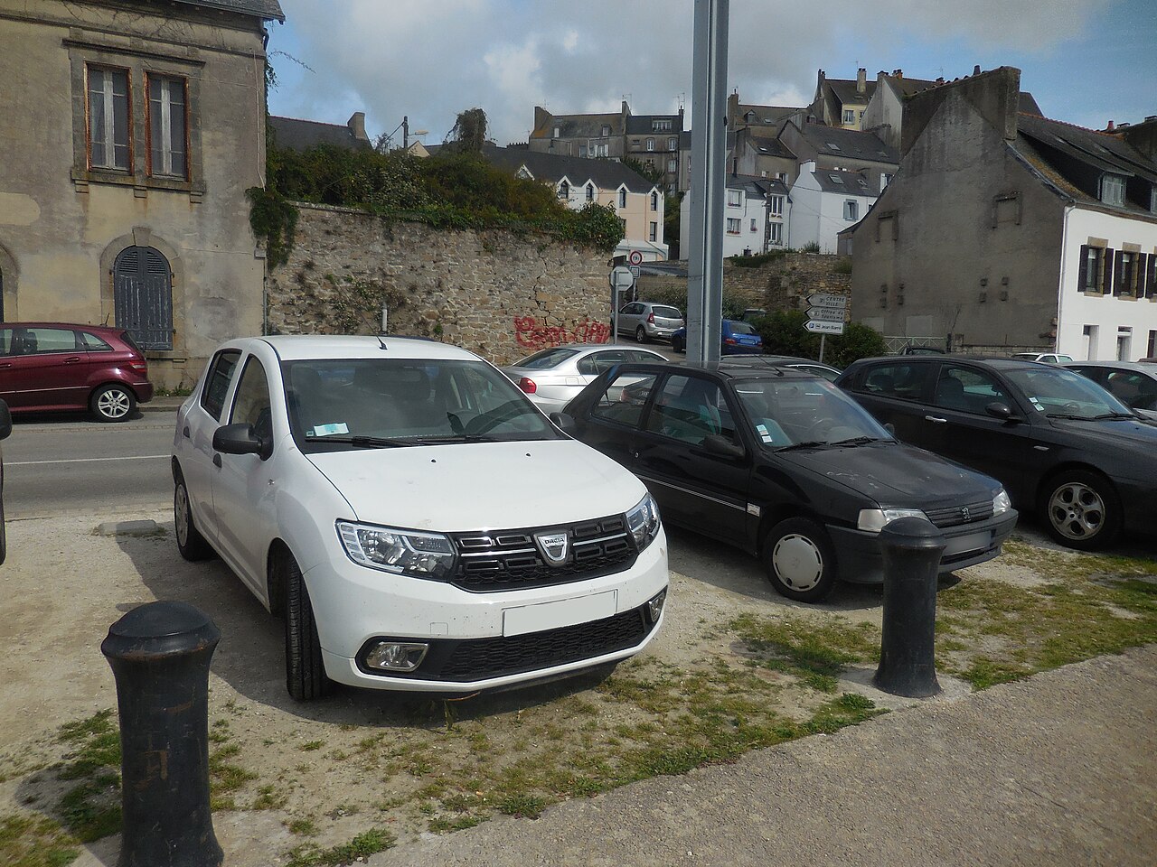
The Dacia Sandero II (X52, 2012-2020) is a hatchback also sold in the higher-riding Sandero Stepway version. The documented fuse layout below has 39 passenger compartment fuses, two cabin relays, 13 under-bonnet fuses and five front-compartment relays, with original position labels and ratings preserved.
Different petrol, diesel and LPG engines (including 1.2, 0.9 TCe, 1.0 SCe and dCi), model years, facelift changes and trim packages can alter the fitted circuits. This is one documented second-generation arrangement, not a guarantee that every 2012-2020 Sandero uses identical positions. Compare the actual cover label and vehicle-specific documentation.
Where are the Dacia Sandero II fuse boxes?
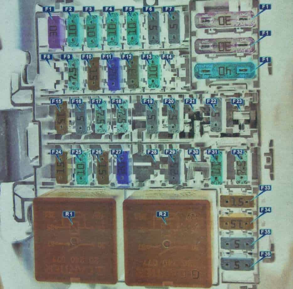
Passenger compartment: open the driver door to access the fuse-panel cover at the side of the dashboard. With the ignition off, release the cover and compare the positions F1-F39 with its legend. This panel protects lighting, power windows, door locks, audio, wipers and the 12 V socket.
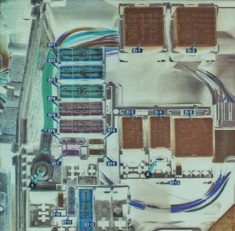
Engine compartment: the covered fuse and relay box is near the auxiliary battery. Its large fuse entries use labels Ef1-Ef13, whereas relays use Er1-Er5. These are separate from the F-numbered dashboard circuits. Some engine types and Stepway equipment have different relay fitment.
Dacia Sandero II passenger compartment fuse box F1-F39
The table reproduces all 39 fuse positions from the documented second-generation configuration, including several spare or empty sockets. F33 (15 A) protects the cigarette lighter and 12 V accessory socket. The left and right dipped-beam headlamps use F4 and F5, while separate F2 and F3 protect the high beams.
| Position | Rating / relay type | Protected circuit / function |
|---|---|---|
| F1 | 30 | Front power windows |
| F2 | 10 | Left high-beam headlamp |
| F3 | 10 | Right high-beam headlamp |
| F4 | 10 | Left dipped-beam headlamp |
| F5 | 10 | Right dipped-beam headlamp |
| F6 | 5 | Rear position lights and instrument panel illumination |
| F7 | 5 | Front position lights |
| F8 | 30 | Rear power windows |
| F9 | 7.5 | Rear fog lamp |
| F10 | 15 | Horn |
| F11 | 20 | Central door locking |
| F12 | 3 | ABS/ESP control circuitry |
| F13 | 10 | Interior lighting and air-conditioning control |
| F14 | 5 | Steering angle sensor |
| F15 | 15 | Windscreen washers, parking sensors and reversing lamps |
| F16 | 5 | Audio system, rear window heating and cruise control / speed limiter |
| F17 | 7.5 | Daytime running lights |
| F18 | 7.5 | Brake lights |
| F19 | 5 | UCH body control module |
| F20 | 5 | Airbag SRS controller |
| F21 | – | Spare or unoccupied position |
| F22 | – | Spare or unoccupied position |
| F23 | – | Spare or unoccupied position |
| F24 | 15 | Turn signals |
| F25 | 10 | Alarm system, if equipped |
| F26 | 15 | Passenger compartment electrical control module (UCH) |
| F27 | 20 | Steering column switches – dipped-beam control |
| F28 | – | Spare or unoccupied position |
| F29 | 25 | Steering column switches – high-beam control |
| F30 | – | Spare or unoccupied position |
| F31 | 10 | Instrument cluster |
| F32 | 7.5 | Audio system |
| F33 | 15 | Cigarette lighter and 12 V accessory socket |
| F34 | 15 | OBD diagnostic connector |
| F35 | 5 | Heated exterior mirrors |
| F36 | 5 | Electric exterior mirror adjustment |
| F37 | 30 | Starter motor |
| F38 | 30 | Front windscreen wipers |
| F39 | 40 | Cabin heater and air-conditioning blower |
Cabin relays R1-R2
R1 and R2 are relays rather than conventional blade fuses. The chart identifies air-conditioning control and the heated rear-window circuit; the second column retains the original 35 A relay specification.
| Position | Rating / relay type | Protected circuit / function |
|---|---|---|
| R1 | Relay, 35 A | Air-conditioning control |
| R2 | Relay, 35 A | Heated rear window |
Dacia Sandero II under-bonnet fuse box Ef1-Ef13
The front compartment provides power to ABS/ESP, cabin distribution, engine management, the heated windscreen, radiator fan and optional front fog lights. Do not confuse Ef numbers with the separate cabin F positions.
| Position | Rating / relay type | Protected circuit / function |
|---|---|---|
| Ef1 | 40 | Right side of the heated front windscreen, if equipped |
| Ef2 | 40 | Left side of the heated front windscreen, if equipped |
| Ef3 | 50 | Main ABS/ESP power supply |
| Ef4 | 60 | Immobiliser and passenger-compartment F28-F31 supply |
| Ef5 | 60 | Passenger-compartment F11, F23-F27, F34 and F39 supply |
| Ef6 | 30 | Secondary ABS/ESP supply |
| Ef7 | 30 | Heated rear window and exterior mirrors |
| Ef8 | 15 | Front fog lamps |
| Ef9 | 15 | Heated seats, if equipped |
| Ef10 | 15 / 25 | Air-conditioning compressor clutch (15 A) or first cooling fan speed without air conditioning (25 A) |
| Ef11 | 25 | Main engine control relay supply |
| Ef12 | 40 | Radiator cooling fan |
| Ef13 | 15 | Engine control unit and engine management |
Important powertrain difference: Ef10 can use 15 A for the air-conditioning compressor clutch, or 25 A for the first cooling fan speed in a version without air conditioning. These ratings are alternatives for different configurations, not interchangeable replacements.
Engine compartment relays Er1-Er5
The front relays serve heated windscreen sections, fuel pump, air-conditioning compressor or cooling fan, and the main engine management supply. The source documents five assignments; not all may be fitted to every Sandero II.
| Position | Rating / relay type | Protected circuit / function |
|---|---|---|
| Er1 | Relay, 35 A | Left side of heated front windscreen |
| Er2 | Relay, 35 A | Right side of heated front windscreen |
| Er3 | Relay, 20 A | Fuel pump |
| Er4 | Relay, 20 A | Air-conditioning compressor or first radiator fan speed, depending on equipment |
| Er5 | Relay, 35 A | Main engine control unit relay |
Commonly searched fuses: 12 V socket, radio, wipers and lights
12 V socket or cigarette lighter: inspect cabin F33 (15 A). Radio: cabin F32 (7.5 A), and depending on vehicle equipment, F16 (5 A). Windscreen wipers: cabin F38 (30 A); washer supply: F15 (15 A).
Horn: cabin F10 (15 A). Central locking: cabin F11 (20 A). Starter: cabin F37 (30 A), although a no-start condition also requires battery, earthing and control diagnostics. The fuel pump relay is identified as Er3; engine management uses Ef11, Ef13 and relay Er5.
Headlights: cabin F2 (10 A) left high beam and F3 (10 A) right high beam. F4 (10 A) protects the left dipped beam; F5 (10 A) protects the right dipped beam. Keeping high-beam and dipped-beam assignments separate matters when tracing a lighting failure.
Sandero, Stepway, facelift and related hatchbacks
The Sandero II was supplied with several engine and equipment revisions, including LPG variants and the 2017-2020 facelift. One or more fuse slots may differ across those cars. Always follow the configuration corresponding to your VIN and the actual fuse-box cover; never fit a fuse of higher amperage than specified.
For a different Dacia generation, see the Dacia Logan I fuse guide. For another hatchback popular in Europe, see the Skoda Scala 2019-2020 fuse diagrams. These cars use unrelated electrical systems, so their fuse positions cannot be substituted for one another.
Dacia Sandero II fuse box FAQ
Where is the dashboard fuse box?
Behind the removable side panel of the dashboard accessible when the driver door is open.
Which fuse protects the cigarette lighter or 12 V socket?
Cabin F33, rated at 15 A, in the documented Sandero II configuration.
Where is the horn fuse?
Cabin F10, rated at 15 A. If that fuse is intact, inspect the horn and related controls.
Are the Ef10 ratings always the same?
No. The documented configuration lists 15 A for the air-conditioning compressor clutch or 25 A for the first cooling fan speed without air conditioning.
Can these diagrams be used for every Sandero Stepway?
Not automatically. Equipment, engine type, market and production year can alter the installed circuits.
Featured vehicle photograph: Antoineets, Wikimedia Commons, CC BY-SA 4.0; photographed in 2017 and resized to 1280 px. Fuse information: documented Dacia Sandero II / Stepway second-generation fuse and relay arrangements.